ngs
DM32000 DM32010 8200 1:N NT Link mode
DM32001 DM32011
0000 to 0009
(*1)
Communications baud rate
(standard)
DM32006 DM32016 000j
j = The largest model number of
the connected PT (0 – 7)
*1 Set any value between 0000 and 0009 Hex for the communications baud rate.
The same baud rate will be used regardless of the value as long as it is between
0000 and 0009 Hex.
For
example, when connecting PT
s with model
numbers 3, 4, 5, and 6 to port 1,
set
DM 32000 to 8200 Hex, DM 32001 to 0000 Hex, and DM 32006
to 0006 Hex.
Connecting to CS/CJ-series Serial Communications Unit
A CS-series Rack-mounted Unit: CS1W-SCU21
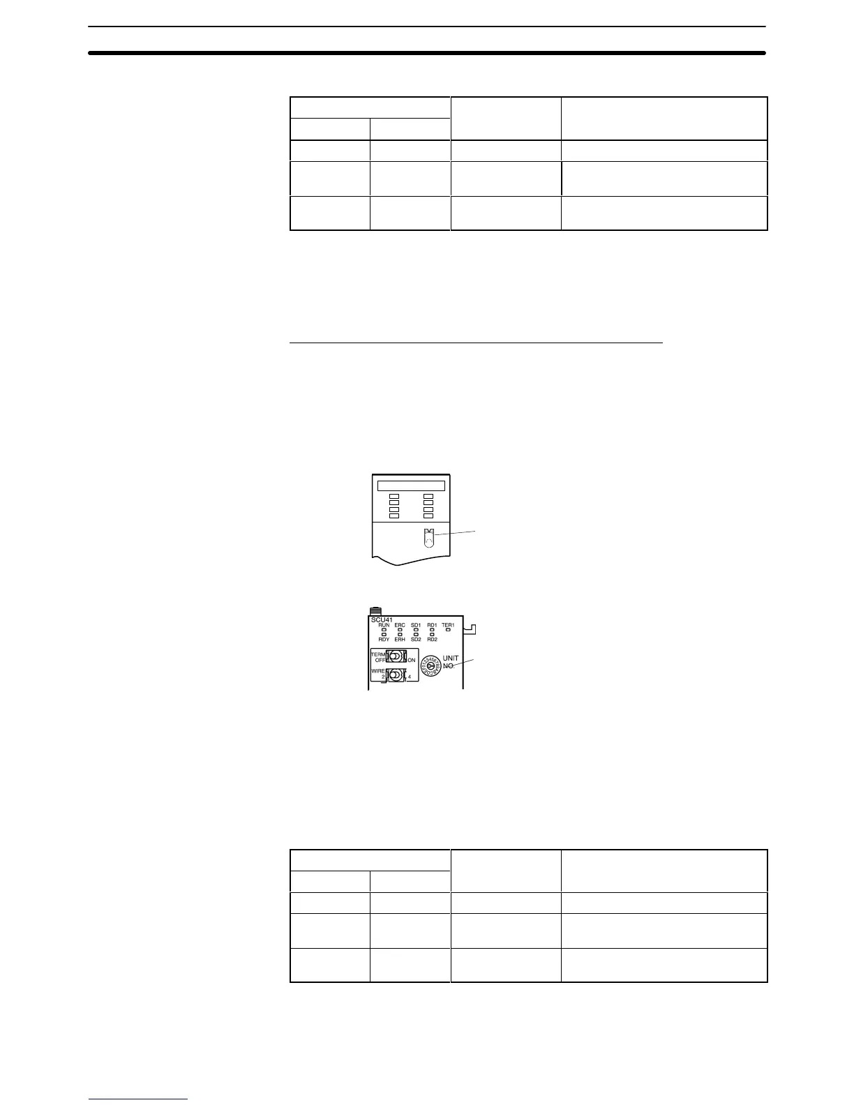
CJ-series: CJ1W-SCU41 (Port 2 is an RS-232C port.)
Setting the Front Switches
Set
the unit number of the Serial
Communications Unit by using the rotary switch
located
on the front panel. Set each switch with a flat blade screwdriver so
that
the values or symbols in the setting value window agree with the following.
Set
the unit number to 0 through F so
that it will not duplicate the numbers
used in other Units.
SCU21
RUN
ERC
SD1
RD1
RDY
ERH
SD2
RD2
No.
F
E
D
C
B
A
9
8
7
6
5
4
3
2
1
0
UNIT
CS1W-SCU21
CJ1W-SCU41
Set the unit number to 0 through F so
that it will not duplicate the numbers
used in other Units.
Allocation DM Area Settings for CPU Unit
Setting
is written from the Programming Device
(a Programming Console or CX-
Programmer) directly into the allocated DM Area (PC Setup) of the CPU Unit.
After
the setting is written, it becomes ef
fective by turning the
power ON, restart
-
ing the Unit, restarting the communication port, or execution of the STUP
instruction.
The
following table shows the words allocated in the DM Area and the settings.
m = DM30000 + (100 × unit number)
Allocated DM word

 Loading...


