8 - 21
8 Pulse Output Units
NX-series Position Interface Units User’s Manual (W524)
8-6 Terminal Block Arrangement
8
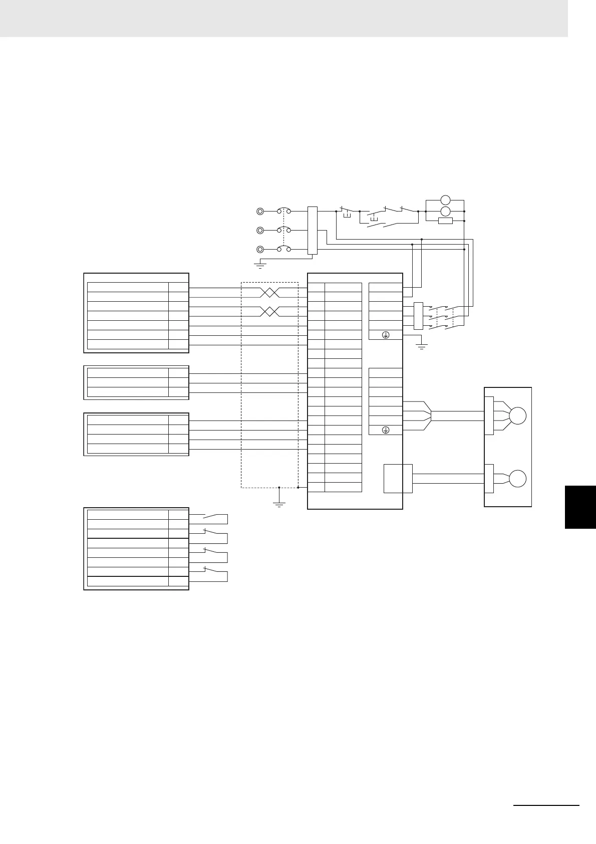
8-6-2 NX-PG0122
OMRON G5-series Servomotor/Servo Drive Wiring Example
This section provides wiring examples for limit inputs and other control I/O in addition to the
NX-PG0122 Pulse Output Unit.
The way these signals are handled depends on the system configuration of the Controller that you
use.
Refer to 8-9 Setting Methods on page 8-39 and Section 9 Application Example for information on
using the MC Function Module in an NJ/NX-series Controller.
Three-phase, 200 to 240 VAC, 50/60Hz
MC2
MC2
SUP
MC2
MC1
MC1
MC2MC1
OFF ON
NFB
MC1
37
/ALM
E
R
S
T
M
CN2
CN1 CNA
CNB
A1
A2
B1
B2
6
1
4
30
19
25
39
7
29
31
38
36
2
+24VCCW
L1C
L2C
L1
L2
L3
B1
B3
B2
U
V
W
+24VCW
Z
INP
+24VIN
RUN
RESET
INPCOM
ALMCOM
FG
A7
A6
ECRST
-CCW
-CW
ZCOM
A3
NX-PG0122
A2
A1
B1
IOG
OUT0
OUT1
NX-OD4256
A1
A2
B1
IN0
IOV
IN1
B2
IOV
NX-ID3417
A1
A2
B1
IN0
IOV
IN1
B2
IOV
A4
A5
B4
IN2
IOV
IN3
B5
IOV
NX-ID3417
Reactor
Motor power cable
R88M-K
Red
Green/Yellow
White
Blue
Encoder cable
Shell
Main power supply
Ground to less
than 100 Ω.
Main circuit contactors
Surge suppressor
Noise filter
R88D-KT
Pulse output A
Pulse output 0 V
Pulse output 0 V
External output 0
External input 0
Sensor power supply output, 24 V
Pulse output B
Home proximity input
Positive limit input
Negative limit input
Immediate stop input
 Loading...


