8 - 35
8 Pulse Output Units
NX-series Position Interface Units User’s Manual (W524)
8-8 I/O Data Specifications
8
8-8-2 Data Details
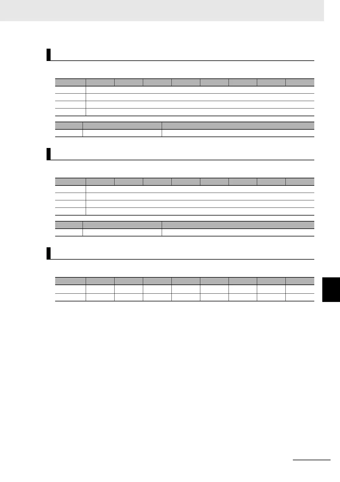
The bit configuration of the Latch Input 1 Data variable is given in the following table.
The bit configuration of the Latch Input 2 Data variable is given in the following table.
The bit configuration of the Controlword is given in the following table.
Latch Input 1 Data
Byte Bit 7 Bit 6 Bit 5 Bit 4 Bit 3 Bit 2 Bit 1 Bit 0
0 ELV1 (Latch Input 1 Data LL)
+1 ELV1 (Latch Input 1 Data LH)
+2 ELV1 (Latch Input 1 Data HL)
+3 ELV1 (Latch Input 1 Data HH)
Abbr. Data Description
ELV1 Latch Input 1 Data This contains the latch 1 data.
Latch Input 2 Data
Byte Bit 7 Bit 6 Bit 5 Bit 4 Bit 3 Bit 2 Bit 1 Bit 0
0 ELV2 (Latch Input 2 Data LL)
+1 ELV2 (Latch Input 2 Data LH)
+2 ELV2 (Latch Input 2 Data HL)
+3 ELV2 (Latch Input 2 Data HH)
Abbr. Data Description
ELV2 Latch Input 2 Data This contains the latch 2 data.
Controlword
Byte Bit 7 Bit 6 Bit 5 Bit 4 Bit 3 Bit 2 Bit 1 Bit 0
0
fr
*1
*1. “fr” is an abbreviation for Fault Reset.
--- --- ---
eo
*2
*2. “eo” is an abbreviation of Enable Operation.
qs
*3
*3. “qs” is an abbreviation for Quick Stop Done.
ev
*4
*4. “ev” is an abbreviation of Enable Voltage.
so
*5
*5. “so” is an abbreviation of Switch ON.
+1 --- --- --- --- --- --- --- ---