8 Pulse Output Units
8 - 36
NX-series Position Interface Units User’s Manual (W524)
Controlword Status
When a Fault Reset is executed with bit 7, set the bit back to 0 before giving the next command.
The bit configuration of the External Output variable is given in the following table.
Note You can assign the External Output object to I/O data to control its ON/OFF state. However, when the Unit
is assigned to an MC Function Module axis and the External Output 0 Function Selection parameter is set
to Error counter reset, the external output is controlled automatically through the latch function. You cannot
turn it ON and OFF directly.
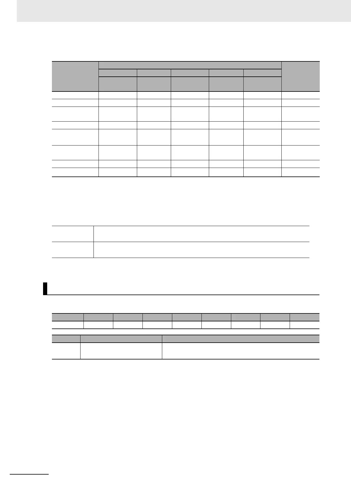
Command
Controlword bits
Number in
transition
diagram
*1
*1. Refer to 8-3-1 Control State on page 8-5 for the transition diagram.
Bit 7 Bit 3 Bit 2 Bit 1 Bit 0
Fault Reset
Enable
Operation
Quick Stop
Done
Enable
Voltage
Switch ON
Shutdown --- --- 1 1 0 2, 6, or 8
Switch ON --- 0 1 1 1 3
Switch ON +
Enable Operation
--- 1 1 1 1
3 + 4
*2
*2. When the Servo is ready (Switched ON), the Servo is automatically turned ON (Operation Enabled).
Disable Voltage --- --- --- 0 --- 7, 9, or 10
Quick Stop Done --- --- 0 1 --- Not sup-
ported.
*3
*3. The Quick Stop Done command is not supported. Even if a Quick Stop Done command is received, it will be
ignored.
Disable Opera-
tion
--- 0 1 1 1 5
Enable Operation --- 1 1 1 1 4
Fault Reset
0 to 1
*4
*4. This is the operation when bit 7 (Fault Reset) turns ON.
--- --- --- --- 13
Fault state • When the error is reset, the Switch ON Disabled state is entered.
• This state is reset when bit 7 (Warning) in the Statusword (6041 hex) turns ON.
Not Fault state • This state is reset when bit 7 (Warning) in the Statusword (6041 hex) turns ON.
• The state will change according to command bits 0 to 3.
External Output
Byte Bit 7 Bit 6 Bit 5 Bit 4 Bit 3 Bit 2 Bit 1 Bit 0
0 --- --- --- --- --- --- --- EXO0
Abbr. Data Description
EXO0 External Output 1: Output ON
0: Output OFF

 Loading...


