8 Pulse Output Units
8 - 44
NX-series Position Interface Units User’s Manual (W524)
You can use external inputs 0 and 1 on the Pulse Output Unit as external latch inputs 1 and 2
by setting the External Input Function Selection parameters. If you perform homing with the MC
Function Module, external latch 1 (external input 0) is used as the home input. If you do not use
external latch 2 (external input 1) for latching, select a general input for the External Input Func-
tion Selection parameter. If you select a general input, you can use the external input as a limit
input or other input.
Application Example
If you use the MC Function Module and the latching function of the Pulse Output Unit only
for homing, set the external input 0 of the Pulse Output Unit as the external latch input 1
and use it as the home input. You can set external input 1 as a general input and use it as
the home proximity input or another input. In this case, you can change the settings of the
digital inputs of the MC Function Module to assign the input bits.
Refer to 8-10-6 External Input Function Selection on page 8-65 for the External Input Function
Selection parameters of the Pulse Output Unit. For the digital input settings of the MC Function
Module, refer to the setting examples in 8-9-3 Setting Examples on page 8-47 and 9-3-3 I/O
Assignments and Settings on page 9-9.
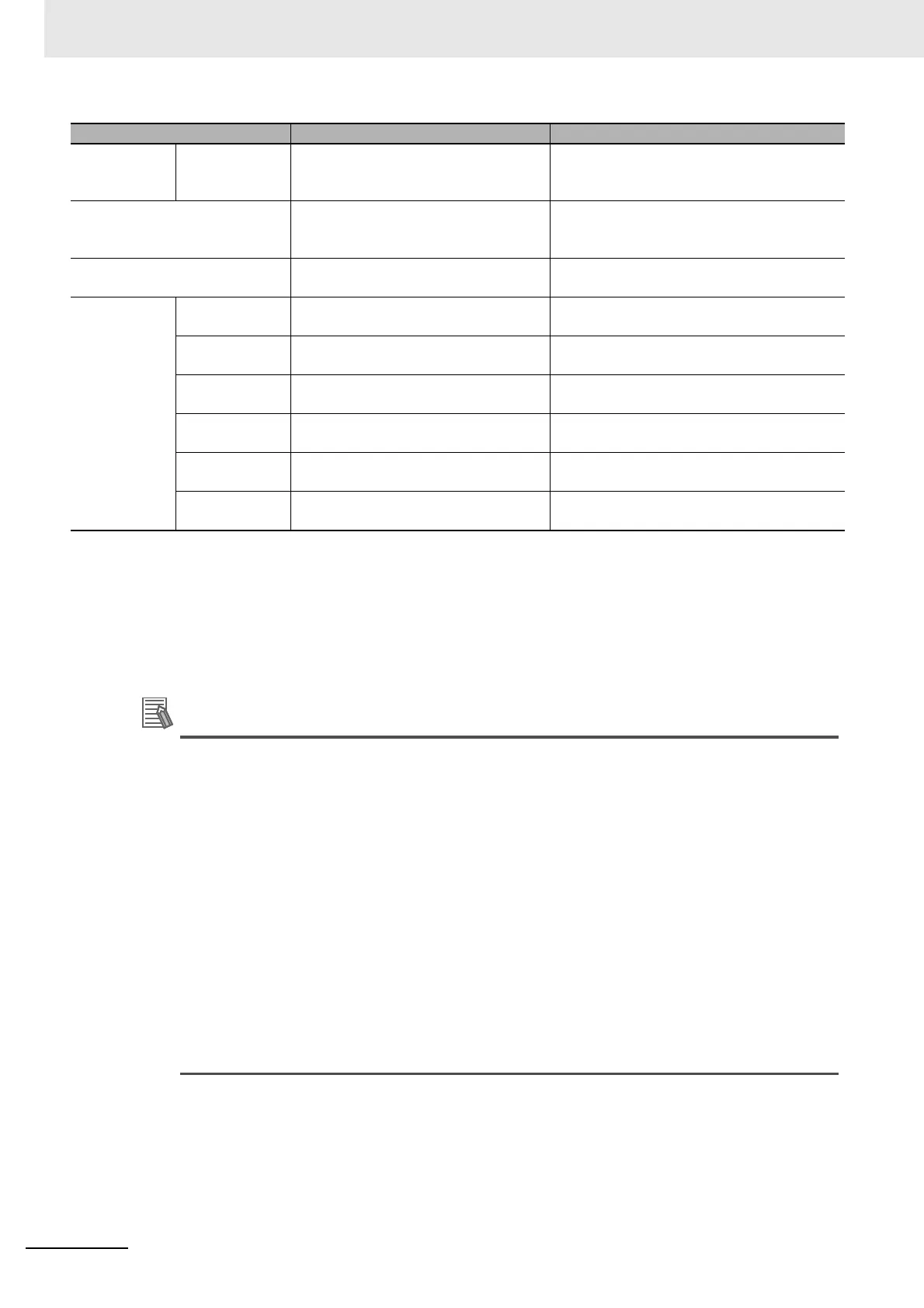
Monitoring
functions
Following error You can monitor the following error in
the Servo Drive.
You cannot monitor the following error in the
motor drive that is connected to a Pulse Out-
put Unit.
Absolute encoder (eliminates the
need to perform homing when the
power is turned ON)
You can use an absolute encoder if you
use an OMRON G5-series Motor with
an Absolute Encoder.
Cannot be used.
Backlash compensation The compensation provided by the
Servo Drive is used.
Cannot be used.
Signal inputs Home input The phase-Z input or external latch
input to the Servo Drive is used.
The latch input on the Pulse Output Unit is
used.
Home proximity
input
The home proximity input on the Servo
Drive is used.
A Digital Input Unit is used. Axis assignment
settings are also required.
Positive limit
input
The positive drive prohibit input to the
Servo Drive is used.
A Digital Input Unit is used. Axis assignment
settings are also required.
Negative limit
input
The negative drive prohibit input to the
Servo Drive is used.
A Digital Input Unit is used. Axis assignment
settings are also required.
Immediate stop
input
The immediate stop input to the Servo
Drive is used.
A Digital Input Unit is used. Axis assignment
settings are also required.
Interrupt input The external latch input to the Servo
Drive is used.
The latch input on the Pulse Output Unit is
used.
*1. Refer to Differences in Processing to Obtain the Actual Current Position on page 8-45 for information on the actual current
position.
*2. This indicates the position that is based on the actual count value from the encoder.
*3. Refer to Differences in Reset Axis Error Processing on page 8-45 for information on resetting axis errors.
*4. This resets the following error through a command operation.
*5. Refer to Differences in In-position Check Processing on page 8-46 for information on in-position checking.
Function When using a G5-series Servo Drive When Using a Pulse Output Unit
 Loading...


