A - 59
Appendices
NX-series Position Interface Units User’s Manual (W524)
A-2 Object Lists
A
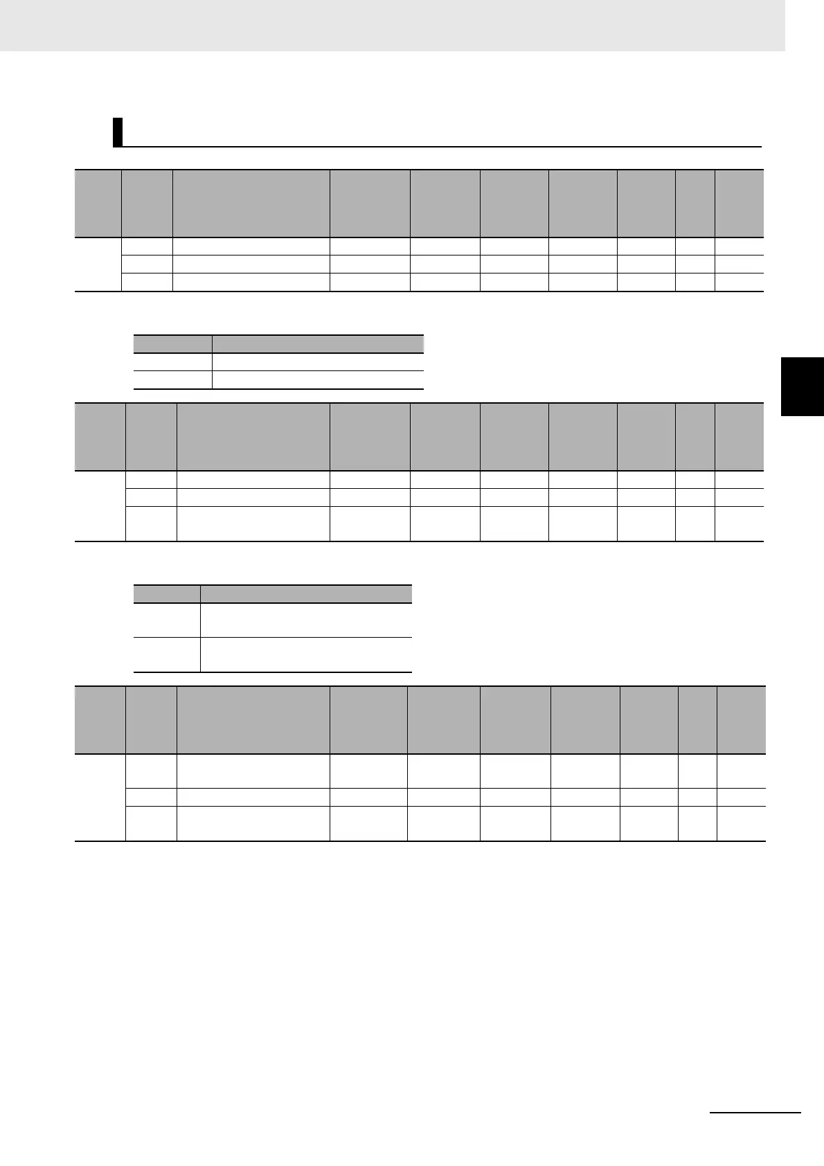
A-2-4 Pulse Output Units
• The following table shows the settings for the Pulse Output Method object.
• The following table shows the settings for the Output Mode Selection object.
• Set this object to the pulse direction change delay.
• This setting is valid only for velocity-continuous pulse output.
Other Objects
Index
(hex)
Subin-
dex
(hex)
Object name Default
Data
range
Unit Data type Access
I/O
allo-
cat-
ion
Data
attri-
bute
5000 --- Pulse Output Method No --- --- --- --- --- ---
00 Number of Entries 1 1 --- USINT RO No ---
01 Ch1 Pulse Output Method 0 0 or 1 --- USINT RW No Y
Set value Description
0 Forward/reverse direction pulse
1 Pulse + Direction
Index
(hex)
Subin-
dex
(hex)
Object name Default
Data
range
Unit Data type Access
I/O
allo-
cat-
ion
Data
attri-
bute
5001 --- Output Mode Selection No --- --- --- --- --- ---
00 Number of Entries 1 1 --- USINT RO No ---
01 Ch1 Output Mode Selec-
tion
0 0 or 1 --- USINT RW No Y
Set value Description
0 Position-synchronous pulse output
(for servomotor control)
1 Velocity-continuous pulse output (for
stepping motor control)
Index
(hex)
Subin-
dex
(hex)
Object name Default
Data
range
Unit Data type Access
I/O
allo-
cat-
ion
Data
attri-
bute
5002 --- Pulse Direction Change
Delay
--- --- --- --- --- --- ---
00 Number of Entries 1 1 --- USINT RO No ---
01 Ch1 Pulse Direction
Change Delay
5 5 to 4,000 μsUINTRWNoY

 Loading...


