7 - 23
7 Digital Output Units
NX-series Digital I/O Unit User’s Manual (W521)
7-6 Precautions when Using the Relay Output Units
7
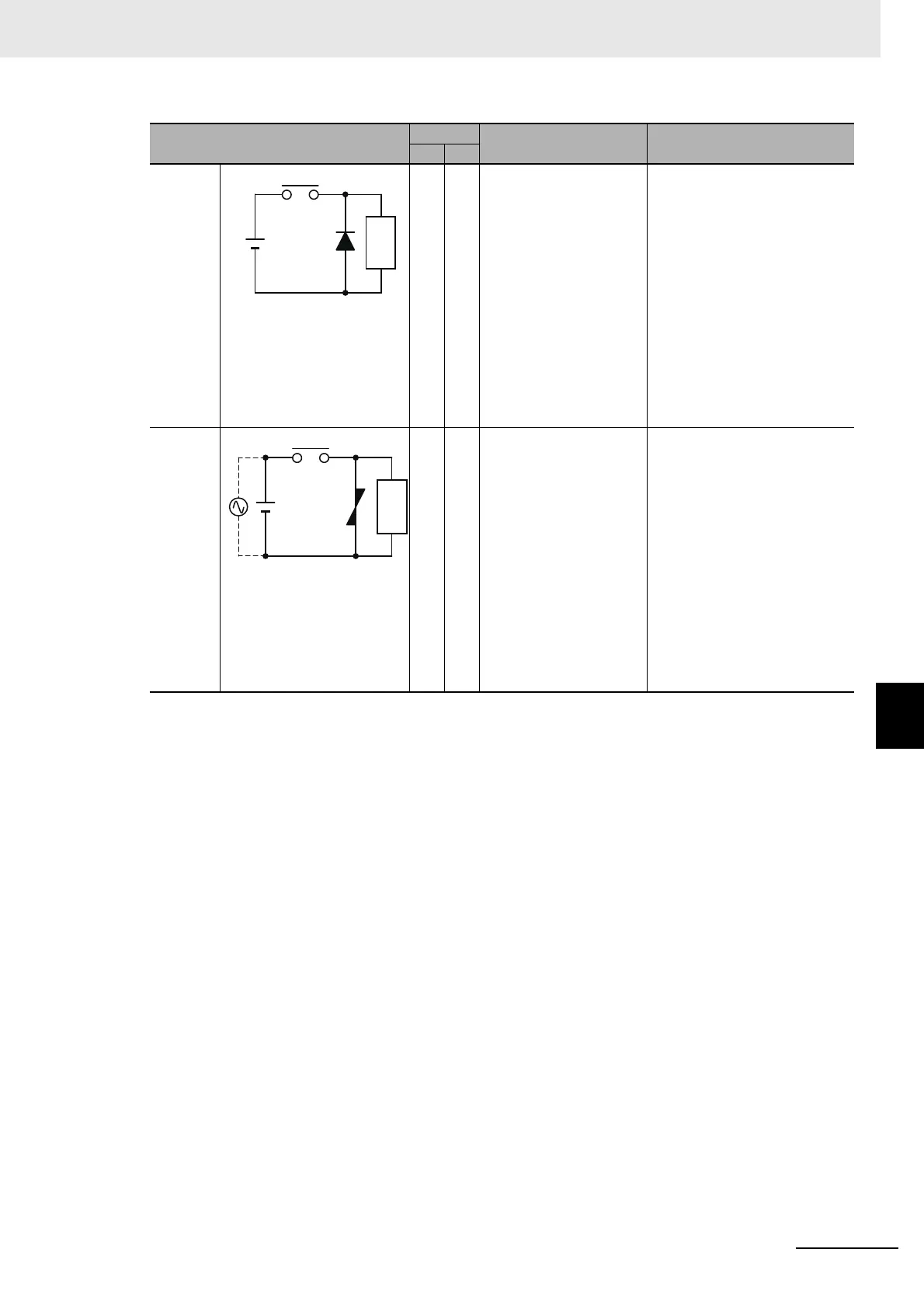
Diode
method
× Yes The diode connected in
parallel with the load
changes energy accu-
mulated by the coil into a
current, which then flows
into the coil so that the
current will be converted
into Joule heat by the
resistance of the induc-
tive load.
The delay in resetting
time caused by this
method is longer than
that caused by the CR
method.
The reversed dielectric strength
value of the diode must be at
least 10 times as large as the
circuit voltage value. The for-
ward current of the diode must
be the same as or larger than
the load current.
The reversed dielectric strength
value of the diode may be two
to three times larger than the
power supply voltage if the con-
tact protection circuit is applied
to electronic circuits with low
circuit voltages.
Varistor
method
Yes Yes The varistor method pre-
vents the imposition of
high voltage between the
contacts by using the
constant voltage charac-
teristic of the varistor.
There is a delay in the
resetting time.
If the power supply volt-
age is 24 to 48 V, insert
the varistor in parallel
with the load. If the sup-
ply voltage is 100 to 200
V, insert the varistor
between the contacts.
-
Circuit
Current
Feature Required element
AC DC
 Loading...