7 Digital Output Units
7 - 22
NX-series Digital I/O Unit User’s Manual (W521)
The life of the Relay varies with the load inductance.
If any inductive load is used, we recommend that you use a contact protection circuit.
(Contact Protec-
tion Circuit on page 7-22).
Be sure to connect a contact protection circuit in parallel with every DC inductive load that is connected
to the Contact Output Unit because the usage of a contact protection circuit has a significant effect on
the service life of the contact.
Contact protection circuits are used with the Contact Output Unit in order to prolong the life of each
relay mounted to the Contact Output Unit, prevent noise, and reduce the generation of carbide and
nitrate deposits caused by arcs. However, if contact protection circuits are used incorrectly, they can
reduce relay service life. Using a contact protection circuit can also cause a delay in the resetting time
(shut-off time).
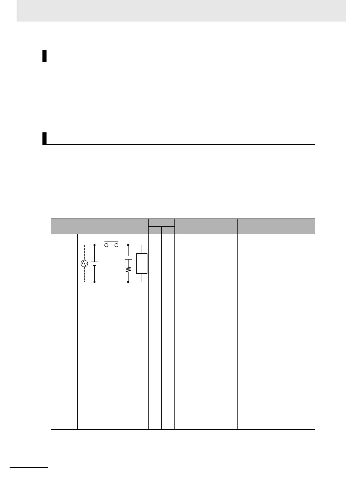
Contact protection circuit examples are listed in the following table.
Inductive Load
Contact Protection Circuit
Circuit
Current
Feature Required element
AC DC
CR
method
Yes Yes If the load is a relay or
solenoid, there is a delay
in the resetting time.
If the power supply volt-
age is 24 or 48 V, con-
nect the contact
protection circuit in paral-
lel with the load. If the
supply voltage is 100 to
200 V, connect the con-
tact protection circuit
between the contacts.
The capacitance of the capaci-
tor should be approx. 1 to 0.5
μF per contact current of 1 A
and resistance of the resistor
should be approx. 0.5 to 1 Ω
per contact voltage of 1 V.
C: The capacitance of the
capacitor should be approx. 0.5
to 1 μF per contact current of 1
A.
R: The resistance of the resis-
tor should be approx. 0.5 to 1 Ω
per contact voltage of 1 V.
These values, however, vary
depending on the load and the
characteristics of the relay.
Decide these values from
experiments, and take into con-
sideration that the capacitance
suppresses spark discharge
when the contacts are sepa-
rated and the resistance
restricts the current that flows
into the load when the circuit is
closed again.
The dielectric strength of the
capacitor must be 200 to 300 V.
If the circuit is an AC circuit,
use a capacitor with no polarity.
Power
supply
C
R
Inductive
load
 Loading...