4 - 29
4 Installation and Wiring
NX-series Digital I/O Unit User’s Manual (W521)
4-3 Wiring the Terminals
4
4-3-1 Wiring to the Screwless Clamping Terminal Block
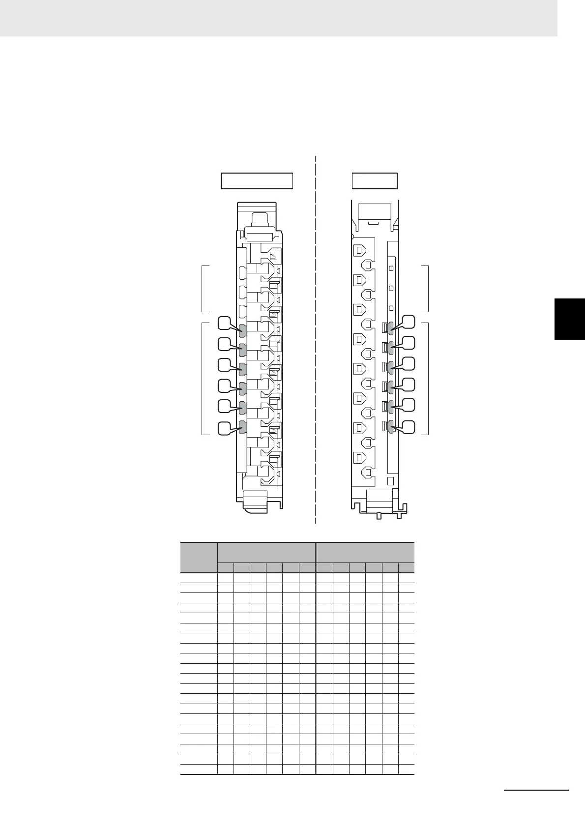
Insertion Locations and Patterns of Coding Pins
Insert three Coding Pins of each on the terminal block and on the Unit at the positions designated by
the numbers 1 through 6 in the figure below.
As shown in the following table, there are 20 unique pin patterns that can be used.
Pin locations for
Terminal Block
○: Pin inserted
Terminal Block Unit
123456
○No.1 ○ ○
○No.2 ○ ○
○No.3 ○ ○
○No.4 ○ ○
○No.5 ○ ○
○No.6 ○ ○
○No.7 ○ ○
○No.8 ○ ○
○No.9 ○ ○
○No.10 ○ ○
No.11 ○ ○ ○
No.12 ○ ○ ○
No.13 ○ ○ ○
No.14 ○ ○ ○
No.15 ○ ○ ○
No.16 ○ ○ ○
No.17 ○ ○ ○
No.18 ○ ○ ○
No.19 ○ ○ ○
No.20 ○ ○ ○
123456
○○○
○○○
○○○
○○○
○○○
○○○
○○○
○○○
○○○
○○○
○○○
○○○
○○○
○○○
○○○
○○○
○○○
○○○
○○○
○○○
1
2
3
4
5
6
1
2
3
4
5
6
Holes used by
OMRON
Holes for incorrect
attachment prevention
(pin locations)
Pin locations for Unit
Pattern
Holes used by
OMRON
Holes for incorrect
attachment prevention
(pin locations)
 Loading...