58
6. Using the UPS monitoring software and contact signal
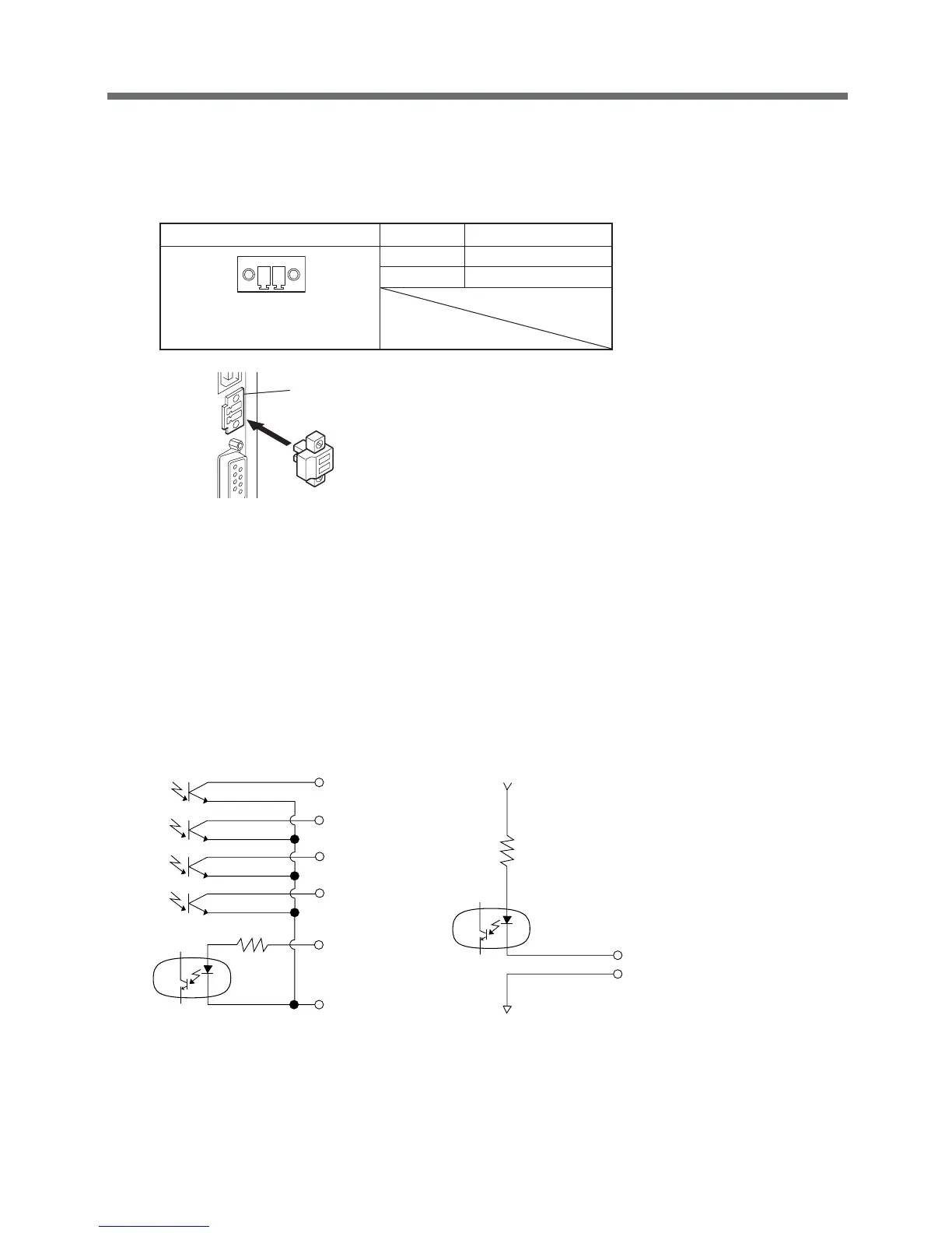
Connector
Connect the remote ON/OFF connector
included with the product.
6. Remote ON/OFF connector (female)
(1) Connect the connector: FUPS Shutdown
Disconnect the connector: FUPS Start-up
(2) The corresponding warning
Remote ON (+)
Remote OFF (--)
10V
BL
TR
BU/NB
BS
COM
2kΩ
WB
Front view
Screw size: Inch screw
#4-40 U N C
Pin assignment Pin number Signal name
1 Remote ON/OFF (+)
2 Remote ON/OFF (--)
1
2
7. Contact Signal ratings
● Signal output (BL, TR, BU/NBU, WB) ● UPS Stop Signal input (BS)
Photo coupler ratings Input voltage HIGH 5 to 15 VDC
Appliable voltage: 35 VDC or less LOW 0.7 VDC or less
Maximum current: 10 mA
● Remote ON/OFF
Voltage between terminals: 10 VDC
Current when closed: max.10 mA
8. Contact Signal circuit inside the UPS
 Loading...


