<BU3002SWG>
<BU3002SWG>
●
Procedure for connection to BU3002SWG output terminal block
When in use, make sure the output terminal block cover is attached.
Do not turn ON the power switch when it is detached.
●
Voltage is applied to the output terminal block when the power switch is ON, which can
result in electric shock.
When connecting a device to the output terminal block, make sure to
include an emergency stop switch (ESD) between them.
●
In the event of an accident, the power supply to the device can be stopped by pressing the
emergency stop switch.
●
A disconnect switch shall be provided by others for ac output terminal block circuit.
●
To reduce the risk of re, connect only to an emer-
gency stop switch (ESD) overcurrent protection for
20 amperes rating in accordance with the National
Electric Code, ANSI/NFPA 70, when using the UPS
as a device conforming to CE standard.
Caution
ESD
emergency stop
switch (ESD)
UPS Load
(1) Remove the terminal block cover on the lower right side of the unit’s
rear panel.
(2) Remove the transparent cover.
(3) Connect the units that need to be backed up.
Two-line connection can be made.
1) To turn ON/OFF at the same timing as that of output receptacle A:
L1A terminal: Connect the line
L2 terminal: Connect the neutral line
2) To turn ON/OFF at the same timing as that of output receptacle B:
L1B terminal: Connect the line
L2 terminal: Connect the neutral line
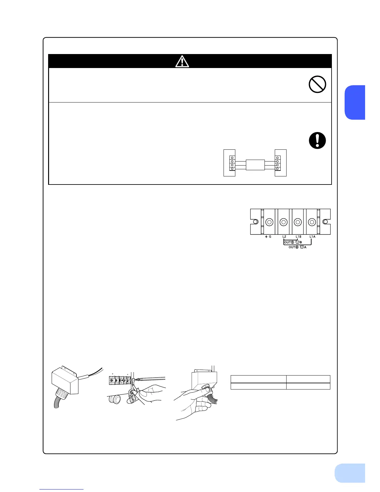
(4) Run the wires to be connected through the hole in the included terminal block cover (with cable
clamp and cable guard tube).
(See Figure 1.)
Connect the ground wire to the G terminal.
Use a Phillips screwdriver to remove the terminal block screws, and connect the wire attached to the
round pressure terminal. (See Figure 2.)
Refer to Table 1 for round pressure terminal sizes.
Figure 1
Table 1
Diameter of screw M5 Screw
Tightening torque 2 Nm(17.7 lb-in)
(5) Cover the terminal block with terminal block cover (with cable clamp) , and fasten the
previously removed screws to the two locations on the upper side of the cover.
Tighten the cable clamp dial to stabilize the wire. (See Figure 3.)
Figure 2 Figure 3