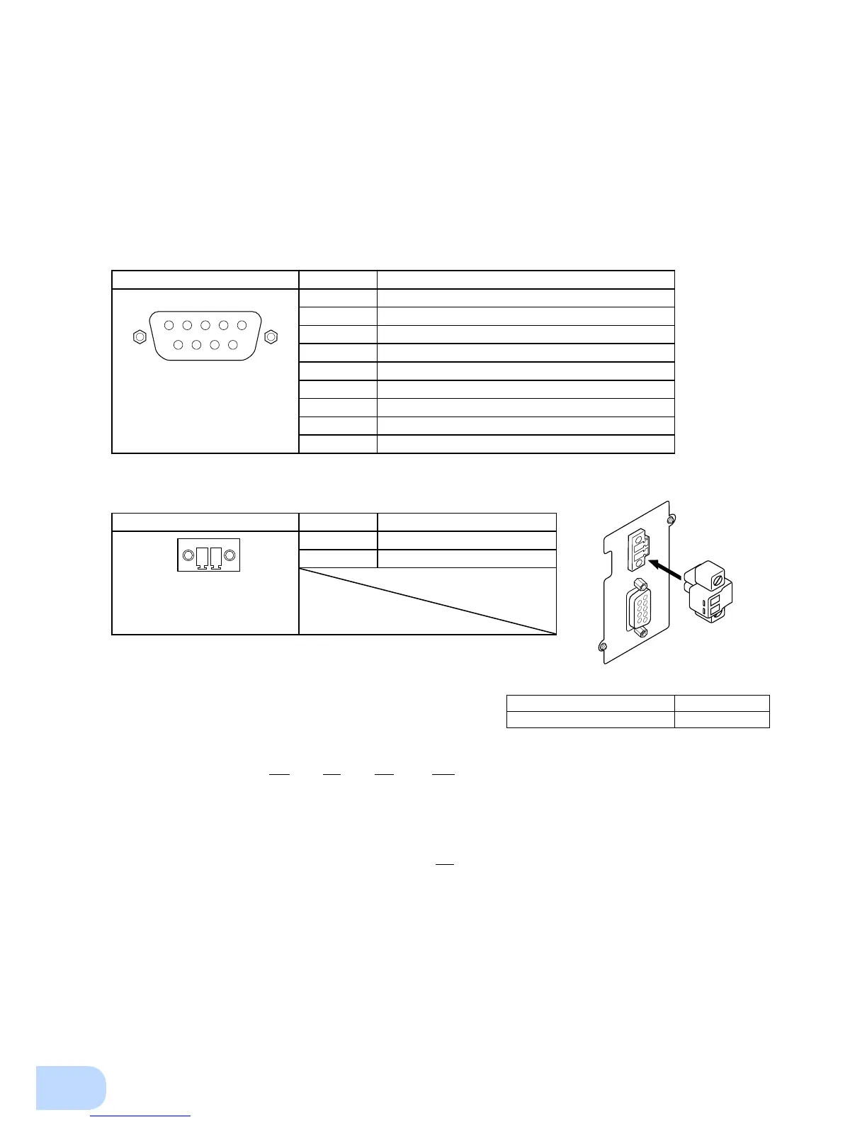
Use a wire that conforms to Table 1 when using
the remote ON/OFF connector.
Recommended cable size AWG 14 to 28
Amount of stripped wire 6 to 7mm
Table 1
Pin assignment Pin number Signal name
Front view
Screw size: inch screw thread
#4-40 UNC
1 Remote ON/OFF (+)
2 Remote ON/OFF (-)
1
2
■
Setting Switch
l
Functionsettingsusingthesettingswitch
The function of this setting switch varies depending on the UPS equipped with the SC08G.
For details, refer to the “Items that can be set using the contact signal card” in the instruction manual of
the UPS equipped with the SC08G.
(Note 1: All setting switches are set to OFF when shipped from the factory.)
(Note 2: Always set the setting switch 3 to “OFF”. Also, set the setting switch not described in the UPS
instruction manual to “OFF”.)
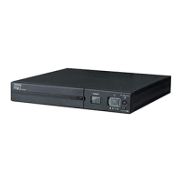
4-4 Signal I/O Connector (Female DSUB 9P)
Pin assignment Pin number Signal name
5 4 3 2 1
9 8 7 6
Front view
Screw size: inch screw thread
#4-40 UNC
1
Backup Signal output-1 (BU-1)
2
Backup Signal output-2 (BU-2)
3
Battery Low signal output-1 (BL-1)
4
Battery Low signal output-1 (BL-2)
5
Trouble signal output (TR)
6
COMMON (TR/WB-COM) of TR and WB signals
7
Battery Replacement Signal output (WB)
8
Backup stop signal input+ (BS+)
9
Backup stop signal input- (BS-)
4-5 Remote ON/OFF connector
4-6 Signal I/O Rating
l
SignalOutput(BU,BU,BL,BL,TR,TR,WB,WB)
Relay rating
Applicable voltage: 30 VDC or less
Maximum current: 2A (under resistive load)
1A (under inductive load)
l
BackupPowerSupplyStopSignalInput(BS,BS)
Input voltage
HIGH (ON) 8 to 24 VDC (at the setting of 24 VDC)
5 to 12 VDC (at the setting of 12 VDC)
LOW(OFF) 0.7 VDC or less
High Sink current at signal input max. 20mA
l
RemoteON/OFF
Voltage between terminals: 5 VDC
Current when closed: max.10 mA