Parameter Details
12
12.3 C: TUNING
SIEPYEUOQ2A01A AC Drive Q2A Technical Manual 577
• Always make adjustments with the load connected to the motor.
• Use analog output signals to monitor U1-16 [SFS Output Frequency] and U1-05 [Motor Speed] when you
adjust the ASR.
■ ASR Adjustment Procedure for Closed Loop V/f Control (CL-V/f)
Do this procedure to adjust ASR parameters:
1. Run the motor at minimum speed and increase C5-03 [ASR PGain 2] as much as possible without oscillation.
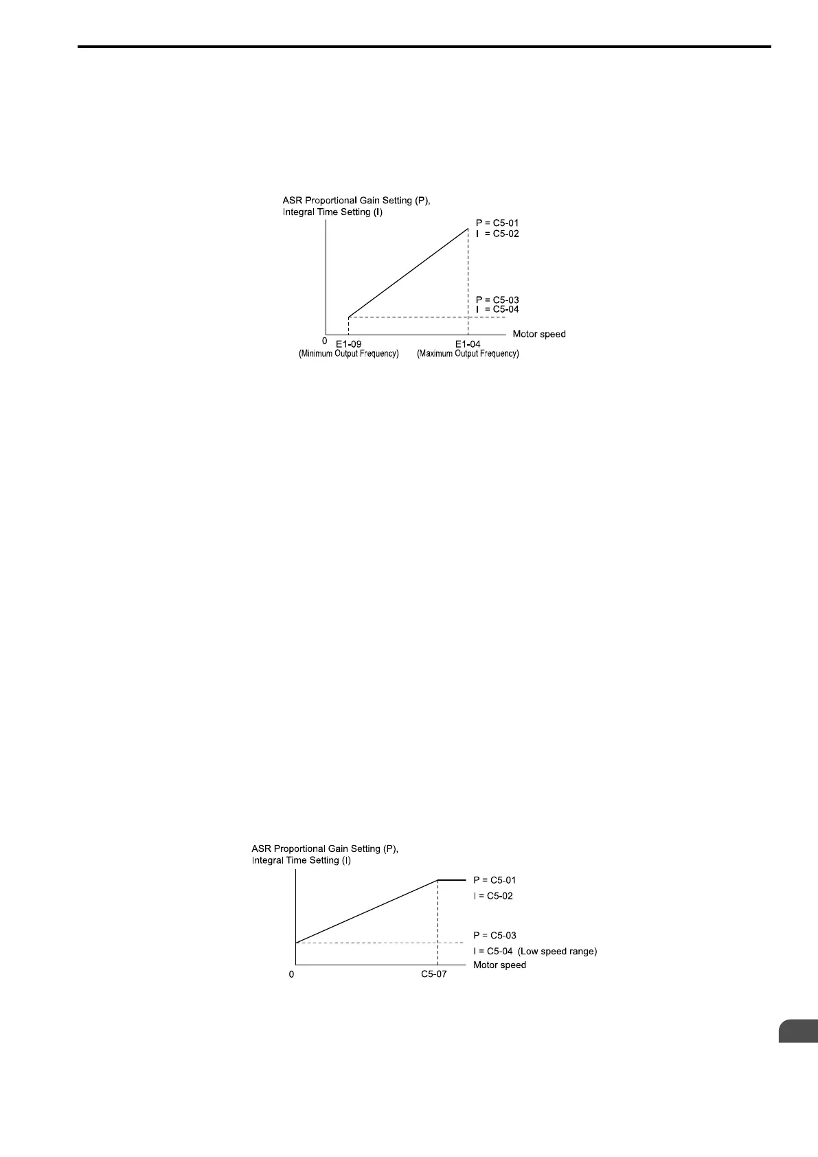
Figure 12.49 ASR Gain and Integral Time Adjustment
2. Run the motor at minimum speed and decrease C5-04 [ASR ITime 2] as much as possible without oscillation.
3. Check the output current monitor to make sure that the output current is less than 50% of the drive rated
current. If the setting value is higher than 50%, decrease C5-03 and increase C5-04.
4. Run the motor at maximum speed and increase C5-01 [ASR PGain 1] as much as possible without
oscillations.
5. Run the motor at maximum speed and decrease C5-02 [ASR ITime 1] as much as possible without
oscillations.
6. If higher speed precision and faster response during acceleration or deceleration are necessary, set C5-12 = 1
[Integral@Ac/Dec Operation = Enabled] to enable integral control during acceleration/decel.
Note:
• If overshooting occurs when acceleration ends, decrease the value set in C5-01 and increase the value set in C5-02.
• If undershoot occurs at stop, decrease C5-03 and increase C5-04.
• If you adjust the gain and it does not correct overshooting and undershooting, decrease the value set in C5-05 [ASR Limit] to decrease
the upper limit of the frequency reference compensation.
■ ASR Adjustment Procedure for CLV, AOLV, AOLV/PM, CLV/PM, and EZOLV
Do this procedure to adjust ASR parameters:
1. Run the motor at zero speed or low speed and increase C5-01 [ASR PGain 1] until immediately before
vibration starts to occur.
2. Run the motor at zero speed or low speed and decrease C5-02 [ASR ITime 1] until immediately before
vibration starts to occur.
3. Check for oscillation when you run the motor at maximum speed.
4. If oscillation occurs, increase C5-02 and decrease C5-01. When there is no oscillation, the adjustment
procedure is complete.
5. Set the low-speed gain. Run the motor at zero speed or low speed and increase C5-03 [ASR PGain 2] until
immediately before vibration starts to occur.
Figure 12.50 Low-speed/High-speed Gain Settings
6. Set the low-speed integral time. Run the motor at zero speed or low speed and decrease C5-04 [ASR ITime 2]
until immediately before vibration starts to occur.
7. Set C5-07 [ASR Gain Switch Frequency].
 Loading...


