12.3 C: TUNING
578 SIEPYEUOQ2A01A AC Drive Q2A Technical Manual
8. Check for oscillation when you run the motor at speeds more than the setting in C5-07.
Note:
• If overshooting occurs when acceleration ends, decrease the value set in C5-01 and increase the value set in C5-02.
• If undershoot occurs at stop, decrease C5-03 and increase C5-04.
■ Use MFDI Switch for Proportional Gain
Note:
If A1-02 = 1 [Control Method = PG V/f Control], you cannot use this function.
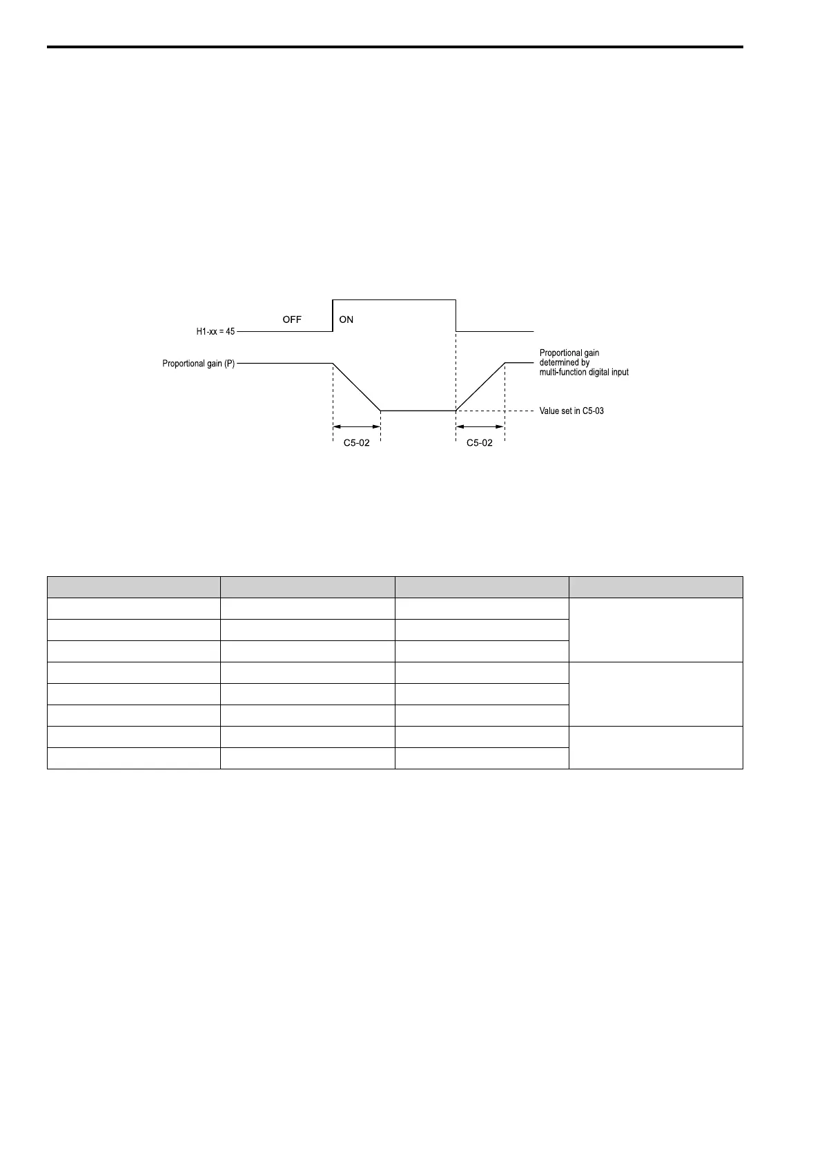
You can use the input terminals set for ASR Gain (C5-03) Select [H1-xx = 45] to switch the proportional gains set
with C5-01 and C5-03. When the configured input terminal is deactivated, the proportional gain set for C5-01 is
selected. When the terminal is activated, the proportional gain set for C5-03 is selected. The proportional gain
changes linearly over the time set in C5-02 [ASR ITime 1]. The signals from this MFDI are more important than
C5-07 [ASR Gain Switch Frequency].
Figure 12.51 Proportional Gain through Multi-function Digital Input Switch
■ Speed Waveform Monitoring Method
To make small adjustments of ASR parameters, monitor the speed waveforms when you make the adjustments.
Table 12.18 shows example settings of parameters to monitor speed waveforms.
Table 12.18 Example Settings of MFAO Terminals to Monitor Speed Waveforms
No. Name Setting Value Description
H4-01 AO1 An.Out Select 116 Lets you use terminal FM to monitor U1-
16 [SFS Output Frequency].
H4-02 AO1 An.Out Gain 100.0%
H4-03 AO1 An.Out Bias 0.0%
H4-04 AO2 An.Out Select 105 Lets you use the terminal AM to monitor
U1-05 [Motor Speed].
H4-05 AO2 An.Out Gain 50.0%
H4-06 AO2 An.Out Bias 0.0%
H4-07 AO1 Signal Level Select 1 Lets you monitor in a -10 to +10 V range.
H4-08 AO2 Signal Level Select 1
These settings cause this MFAO configuration. The MFAO common is terminal A0V:
• Terminal AO1: Outputs the output frequency after SFS in a -10 to +10 V (-100 to +10) range.
• Terminal AO2: Outputs the motor speed in a -10 to +10 V (-200 to +20) range.
The manufacturer recommends that you monitor the output frequency after SFS and the motor speed for delays in
response and differences in reference values.
■ Adjust ASR Parameters
Use Table 12.19 to adjust ASR. The table lists parameters for motor 1, but you can make the same changes to
motor 2 parameters when you run a second motor.
Note:
When adjusting the proportional gain and integral time, adjust the proportional gain first.
 Loading...


