Parameter Details
12
12.7 H: TERMINALS
SIEPYEUOQ2A01A AC Drive Q2A Technical Manual 689
Setting Value Function
3D Comparator 2
3E PID Fbk Low
3F PID Fbk High
4A DC Bus Undervolt
4B FreqRef Loss
4C BrkRes Fault
4D Motor OL1
4E Drive PreOH
4F PreOHTimeLim
60
*2
BrkTransFault
61
*2
BrkTransOH
62 Fan Alarm
Setting Value Function
63 Maintenance
65 WattH Pulse
66 MechWeakDetect
67 ModbusReg 1
69 ModbusReg 2
90 to 93 Q2pack DO1 to 4
A0 to A7 Q2pack ExDO1 to 8
100 to 1A7
Inverse output of 0 to A7
Sets an inverse output of the function for
the MFDO. Put a 1 at the front of the
function setting to set inverse output. For
example, set 138 for inverse output of 38
[TrqDetect2NC].
*1 Inverse output is not available.
*2 You cannot set this parameter on models 4089 to 4675.
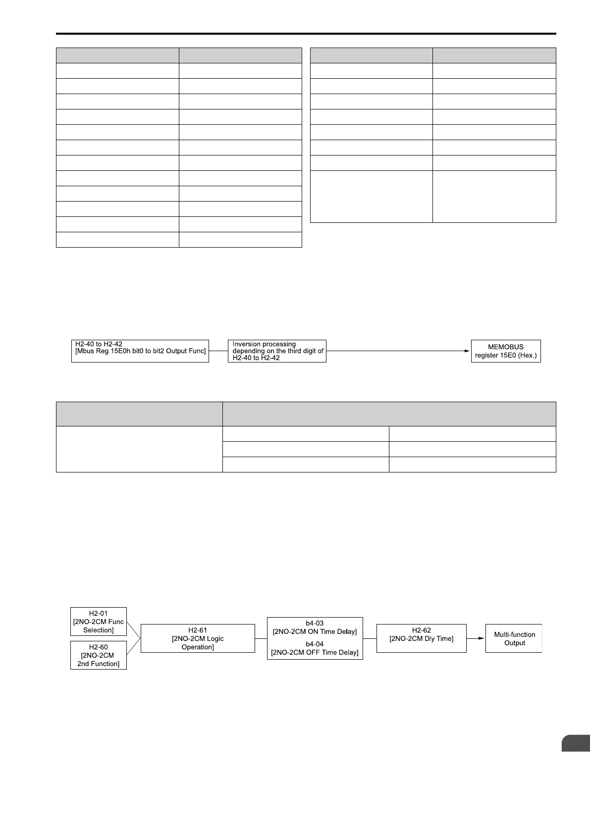
■ Extend MFDO1 to MFDO3 Function Selection
You can set MFDO functions to bit 0 to bit 2 [Mbus MFDO1 to 3] of Modbus register 15E0 (Hex.). Use H2-40 to
H2-42 [Mbus 15E0h b0 Output Function to Mbus 15E0h b2 Output Function] to select the function.
Figure 12.81 Functional Block Diagram of Modbus Multi-function Output
Table 12.47 Modbus MFDO Registers
Register No.
(Hex.)
Name
15E0
bit0 Mbus MFDO 1
bit1 Mbus MFDO 2
bit2 Mbus MFDO 3
Note:
• Refer to H2-xx “MFDO Setting Values” for more information about MFDO setting values.
• When you do not set functions to H2-40 to H2-42, set them to 0.
■ Output of Logical Operation Results of MFDO
This enables the logical operation results of two MFDOs to be output to one MFDO terminal.
Use H2-60, H2-63, and H2-66 [2NO-2CM 2nd Function, 3NO-3CM 2nd Function, 4NO-4CM 2nd Function] to
set the function of the output signal for which logical operations are performed.
Use H2-61, H2-64, H2-67 [2NO-2CM Logic Operation, 3NO-3CM Logic Operation, 4NO-4CM Logic Operation]
to set the logical operation.
Figure 12.82 Functional Block Diagram of Logical Operation Output for MFDO 1
 Loading...


