Parameter Details
12
12.7 H: TERMINALS
SIEPYEUOQ2A01A AC Drive Q2A Technical Manual 731
• Use the frequency reference
When the you do not use the DI, the Forward/Reverse run command is the same as the direction of motor
rotation.
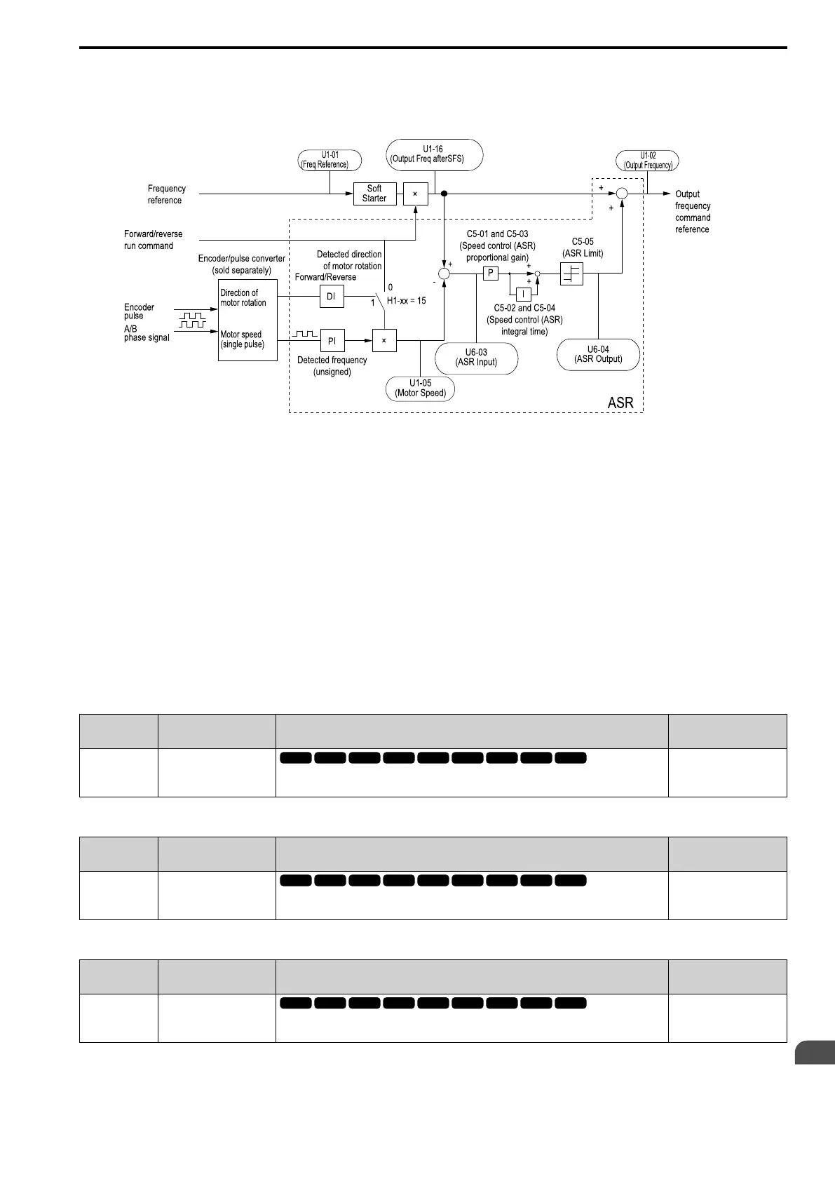
Figure 12.111 shows speed control in Simple Closed Loop V/f Mode.
Figure 12.111 Simple Closed Loop Speed Control Block Diagram
Enable Simple Closed Loop V/f Mode
1. Connect the encoder output pulse wiring to terminal PI.
2. Set A1-02 = 0 [Control Method = V/f Control].
3. Set H6-01 = 3.
4. Set H6-02 [PI Frequency Scale] to the speed feedback (pulse train input signal) frequency at the time when
the frequency reference is 100%.
Make sure that H6-04 [PI Function Bias] = 0% and H6-03 [PI Function Gain] = 100%.
5. Select the detection method for the direction of motor rotation.
When you use an MFDI, set H1-xx = 15.
6. Set C5 parameters related to ASR gain and integral time to adjust responsiveness.
Note:
• Set A1-02 = 0 and H6-01 = 3 to show C5 parameters.
• You cannot use Closed Loop V/f Control mode with the Motor Switch function.
■ H6-02 PI Frequency Scale
No.
(Hex.)
Name Description
Default
(Range)
H6-02
(042D)
RUN
PI Frequency Scale
Sets the frequency of the pulse train input signal used when the function set with H6-01 [PI Pulse
Train Function] is 100%.
1440 Hz
(100 - 32000 Hz)
■ H6-03 PI Function Gain
No.
(Hex.)
Name Description
Default
(Range)
H6-03
(042E)
RUN
PI Function Gain
Sets the gain used when the function in H6-01 [PI Pulse Train Function] is input to terminal PI.
100.0%
(0.0 - 1000.0%)
■ H6-04 PI Function Bias
No.
(Hex.)
Name Description
Default
(Range)
H6-04
(042F)
RUN
PI Function Bias
Sets the bias used when the function in H6-01 [PI Pulse Train Function] is input to terminal PI.
Sets a value when the pulse train is 0 Hz.
0.0%
(-100.0 - 100.0%)
 Loading...


