1 - 37
1 Features and System Configuration
AC Servomotors/Servo Drives 1S-series with Built-in EtherCAT® Communications User’s Manual (I586)
1-7 Procedures to Start Opera-
tion
1
1-7-2 Procedure Details
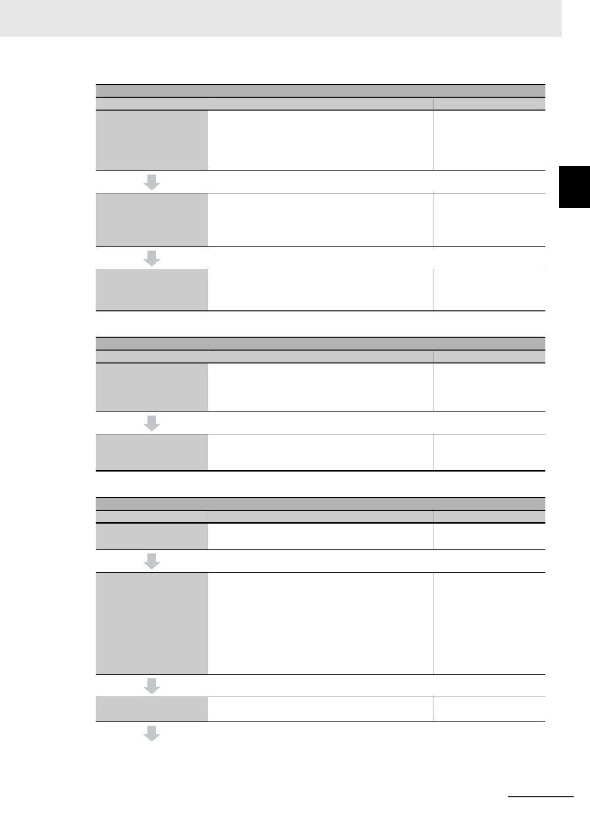
STEP 3 Software and Hardware Design for Safety Control
Procedure Description Reference
STEP 3-1
Determining wiring for
communications, power
supply, and connection
with external I/O devices
Determine wiring used for the communication network,
power supply, and safety I/O devices.
Safety Control Unit User's
Manual
STEP 3-2
Designing I/O and pro-
cessing
Design the configuration of the safety I/O devices and
Safety I/O Unit.
• Safety I/O devices
• Program contents
Safety Control Unit User's
Manual
STEP 3-3
Designing safety pro-
grams
Design POUs (Program Organization Unit).
•Programs
• Function blocks
Safety Control Unit User's
Manual
STEP 4 Calculation and Verification of Safety Control Responsivity
Procedure Description Reference
STEP 4-1
Calculating safety reac-
tion time and safety dis-
tance
Calculate the safety reaction time and then determine
the safety distance.
Safety Control Unit User's
Manual
STEP 4-2
Verifying specification
requirement satisfaction
Verify whether the specification requirements are satis-
fied. If not, reconsider the system design.
Safety Control Unit User's
Manual
STEP 5 Software Design and Programming for Standard Control
Procedure Description Reference
STEP 5-1
Creating project
• Create a new project in the Sysmac Studio.
• Insert a Controller.
NJ/NX-series CPU Unit
User’s Manuals
STEP 5-2
Creating slave and unit
configuration
• Create the slave configuration and Unit configuration
either offline or online.
• Include the safety PDOs (1710 hex and 1B10 hex) in
PDO mapping for the Servo Drive.
• Register the device variables in the variable table.
• Create the axes and set them as real axes or virtual
axes. Create axes groups to perform interpolated
axes control.
NJ/NX-series CPU Unit
User’s Manuals
STEP 5-3
Controller settings
Set PLC Function Modules, Motion Control Function
Modules, etc. in the Sysmac Studio.
NJ/NX-series CPU Unit
User’s Manuals