9 Servo Parameter Objects
9 - 32
G5-series Linear Motors/Servo Drives With Built-in EtherCAT Communications
• Analog signals of various monitor values can be output from the analog monitor connector on the
front panel.
• Set the type of the analog monitor signal output from Analog Monitor Output 1 in the Analog Monitor
1 Selection (3416 hex).
• The scaling (or output gain) can be set as needed in the Analog Monitor 1 Scale Setting (3417 hex).
Setting the Analog Monitor 1 Scale Setting (3417 hex) to 0 automatically applies the output gain as
shown below.
Explanation of Settings
*1 Read the word “torque” as “force.”
*2 The set values shown as “Reserved” must not be used.
For details, refer to 11-1 Analog Monitor on page 11-2.
• Set the output gain for the analog monitor 1.
For details, refer to 11-1 Analog Monitor on page 11-2.
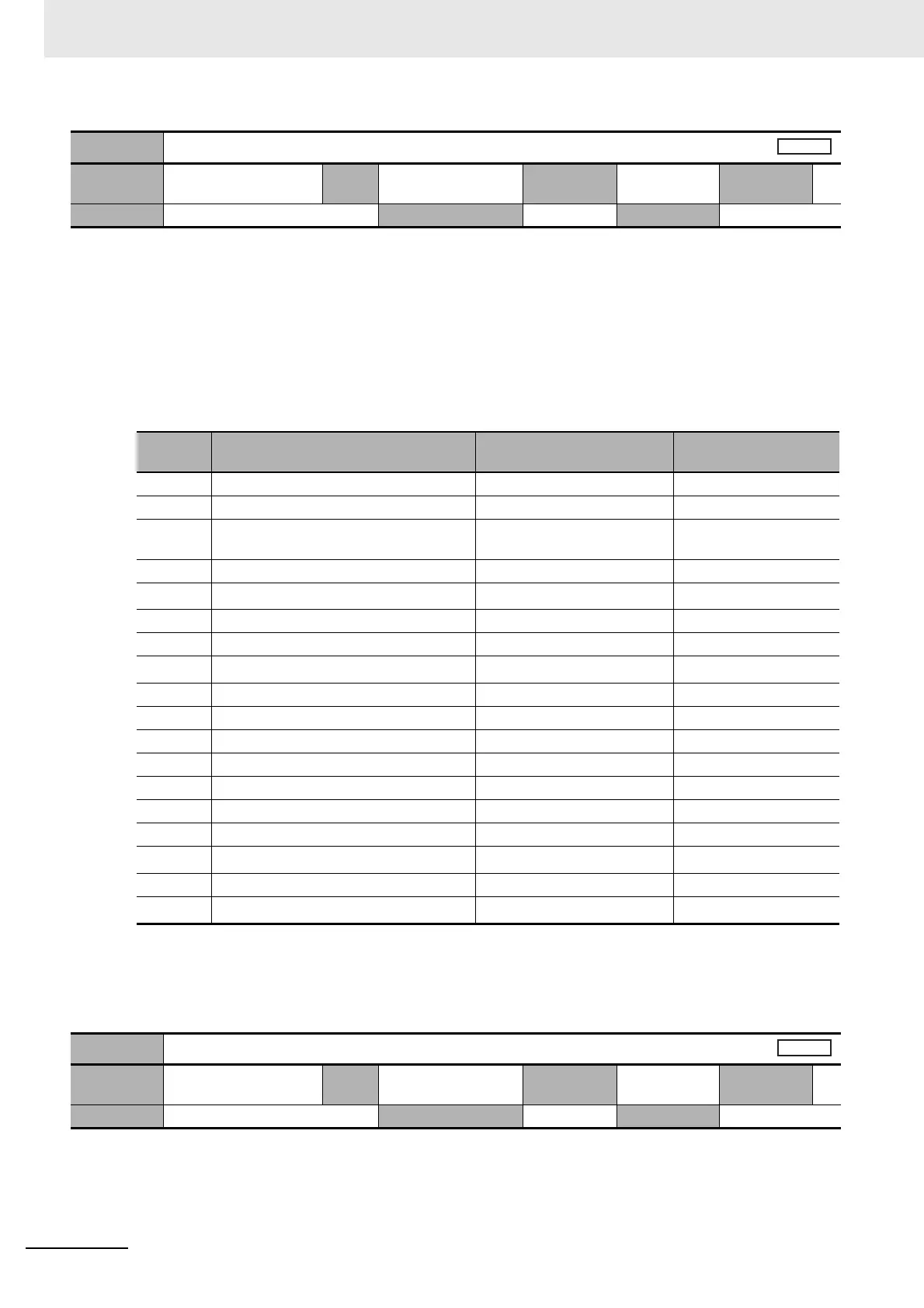
3416 hex
Analog Monitor 1 Selection
Setting
range
0 to 22
Unit
–
Default
setting
0 Data
attribute
A
Size 2 bytes (INT16) Access RW PDO map Not possible
Set value Monitor type Unit
Output gain when
object 3417 hex = 0
0 Motor Velocity Actual Value mm/s 500
1 Motor Velocity Demand Value mm/s 500
2 Motor Velocity Demand Value After
Filtering
mm/s 500
3 Motor Control Effort mm/s 500
4
Torque demand
*1
% (Percentage of rated force) 33
5 Following error actual value Pulse (command unit) 3000
6 Following Error Actual Internal Value Pulse (encoder unit) 3000
7 to 8
Reserved
*2
––
9 P-N voltage V 80
10 Regeneration Load Ratio % 33
11 Motor Load Ratio % 33
12 Positive Force Limit % (Percentage of rated force) 33
13 Negative Force Limit % (Percentage of rated force) 33
14 Speed Limit Value mm/s 500
15 Mass Ratio % 500
16 to 19
Reserved
*2
––
20 Servo Drive Temperature °C 10
21 to 22
Reserved
*2
––
3417 hex
Analog Monitor 1 Scale Setting
Setting
range
0 to 214,748,364
Unit
–
Default
setting
0 Data
attribute
A
Size 4 byte (INT32) Access RW PDO map Not possible

 Loading...
