11-2
11-1 Analog Monitor
OMNUC G5-series AC Servomotors and Servo Drives User’s Manual (with Built-in EtherCAT Communications)
11
Adjustment Functions
11 Motor Load Ratio % 33
12 Forward Torque Limit % 33
13 Reverse Torque Limit % 33
14 Speed Limit Value r/min 500
15 Inertia Ratio % 500
16 to 18 Reserved −−
19 Encoder Temperature
*3
°C10
20 Servo Drive Temperature °C10
21 Encoder 1-rotation Data
*4
pulses (encoder units) 110,000
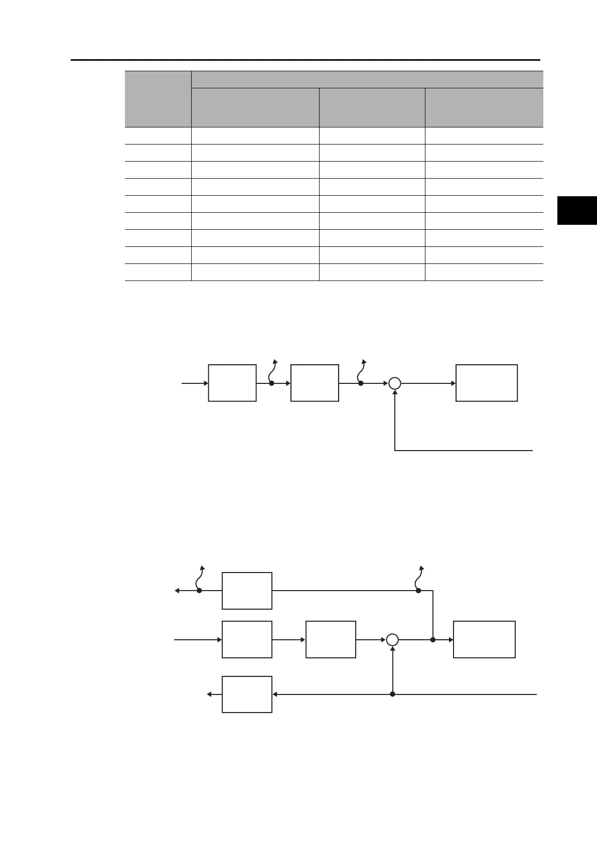
*1. The Internal Command Motor Speed is the speed before the command input passes through the
command filter (the position command filter time constant and the smoothing filter time constant). The
Filtered Internal Command Motor Speed is the speed after the command input passes through the
command filter.
*2. The position error is calculated for the command input after processing for the position command filter.
The pulse position error or fully-closed position error is reversely converted to command units for
application.
The pulse position error or fully-closed error is the error for the position control input.
*3. The encoder temperature is indicated only for a 20-bit incremental encoder. The value is not stable for
other types of encoders.
3416 hex and
3418 hex set
value
Description
Monitoring item Unit
Output gain when 3417
hex and 3419 hex are set
to 0
Command
input
Electronic
gear
Internal Command
Motor Speed [r/min]
Filtered Internal Command
Motor Speed [r/min]
+
−
Position
command
filter
Position
Control
Encoder feedback/external
encoder feedback
Position actual internal
value [encoder
units/external encoder units]
Command
input
Electronic
gear
Pulse Position Error [encoder units]
/Fully-closed Error [external encoder units]
Position
command
filter
Position
control
Encoder feedback/external
encoder feedback
Position Error [command units]
Electronic gear
reverse
conversion
Position actual internal value
[encoder units/external encoder units]
Position actual value
[command units]
Electronic gear
reverse
conversion
+
−
 Loading...
