11-19
11-4 Troubleshooting
OMNUC G5-SERIES AC SERVOMOTOR AND SERVO DRIVE USER'S MANUAL
11
Troubleshooting and Maintenance
36
0
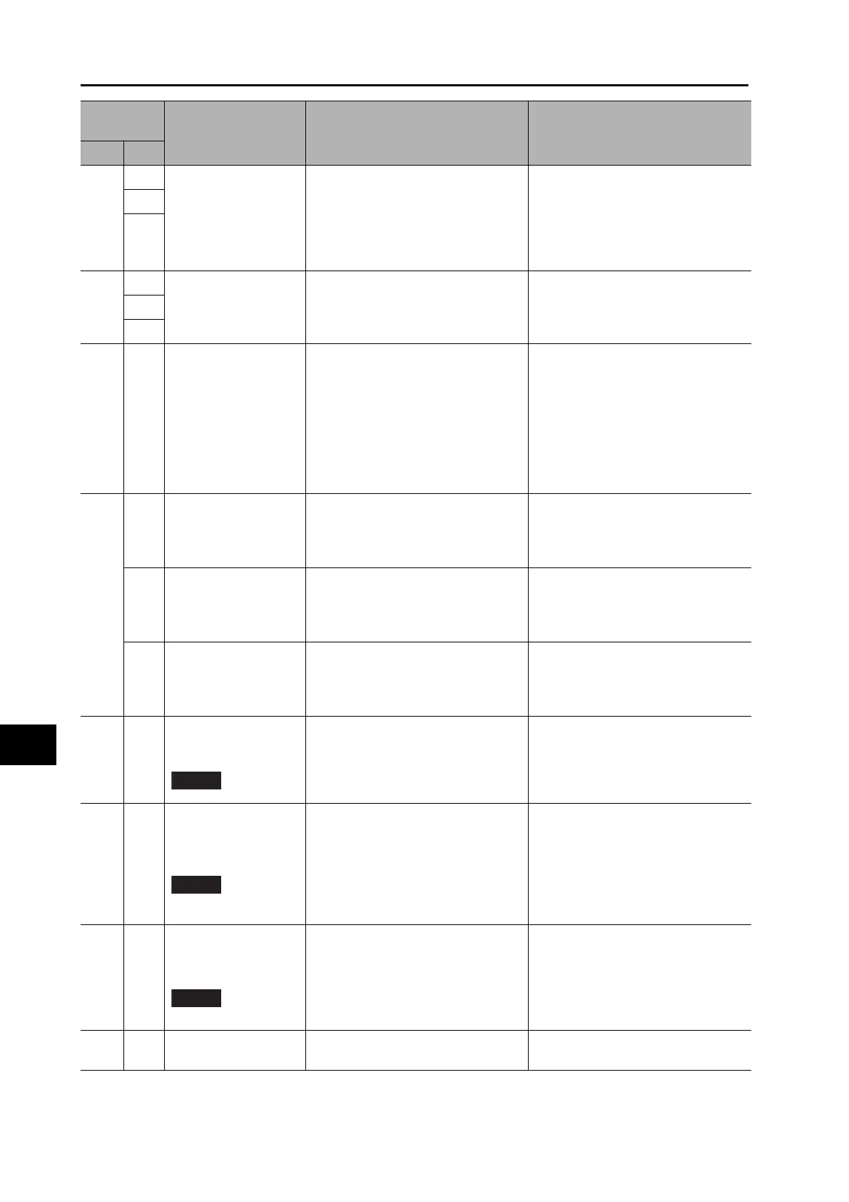
Parameter error
Data in the Parameter Save area was
corrupted when the power supply was
turned ON and data was read from
the EEPROM.
· Reset all parameters.
· If this error occurs repeatedly, the
Servo Drive may be faulty. In this
case, replace the Servo Drive.
Return the Servo Drive to the
dealer that it was purchased from.
1
2
37
0
Parameters
destruction
EEPROM write verification data was
corrupted when the power supply was
turned ON and data was read from
the EEPROM.
The Servo Drive is faulty. Replace the
Servo Drive. Return the Servo Drive
to the dealer that it was purchased
from.
1
2
38 0
Drive prohibition input
error
When the Drive Prohibition Input
Selection (Pn504) was set to 0, both
the Forward Drive Prohibition Input
(POT) and the Reverse Drive
Prohibition Input (NOT) turned ON.
When Pn504 was set to 2, either the
Forward Drive Prohibition input or the
Reverse Drive Prohibition input
turned ON.
Check for any problems with the
switches, wires, and power supplies
that are connected to the forward
drive prohibition input or the reverse
drive prohibition input. In particular,
check to see if the external DC power
supply (12 to 24 VDC) for sequence
inputs turned ON too slowly.
39
0
Excessive analog input
1
A voltage that exceeded the value set
for the Excessive Analog Input 1
(Pn424) was applied to analog input
1.
· Set the Pn424 correctly. Check
the connections to CN1.
· Set Pn424 to 0 to disable alarm
detection.
1
Excessive analog input
2
A voltage that exceeded the value set
for the Excessive Analog Input 2
(Pn427) was applied to analog input
2.
· Set the Pn427 correctly. Check
the connections to CN1.
· Set Pn427 to 0 to disable alarm
detection.
2
Excessive analog input
3
A voltage that exceeded the value set
for the Excessive Analog Input 3
(Pn430) was applied to analog input
3.
· Set the Pn430 correctly. Check
the connections to CN1.
· Set Pn430 to 0 to disable alarm
detection.
40 0
Absolute encoder
system down error
The voltage of the built-in capacitor
dropped below the specified value
because the power supply to the
encoder or the battery power supply
was down.
Connect the battery power supply,
and then clear the absolute encoder.
Unless the absolute encoder is
cleared, the error cannot be reset.
41 0
Absolute encoder
counter overflow error
The multi-rotation counter of the
encoder exceeded the specified
value.
· Set the Operation Switch when
Using Absolute Encoder (Pn015)
to an appropriate value.
· Make sure that the traveling
distance from the origin of the
machine is no more than 32,767
revolutions.
42 0
Absolute encoder
overspeed error
The Servomotor rotation speed
exceeded the specified value when
on
ly the b
attery power supply was
used during a power interruption.
· Check the power supply voltage (5
VDC ± 5%) at the encoder.
· Check the connections to
connector CN2. Unless the
absolute encoder is cleared, the
error cannot be reset.
43 0
Encoder initialization
error
An encoder initialization error was
detected.
Replace the Servomotor.
Alarm
number
Name Cause Measures
Main Sub
 Loading...
