3-46
3-1 Servo Drive Specifications
OMNUC G5-SERIES AC SERVOMOTOR AND SERVO DRIVE USER'S MANUAL
3
Specifications
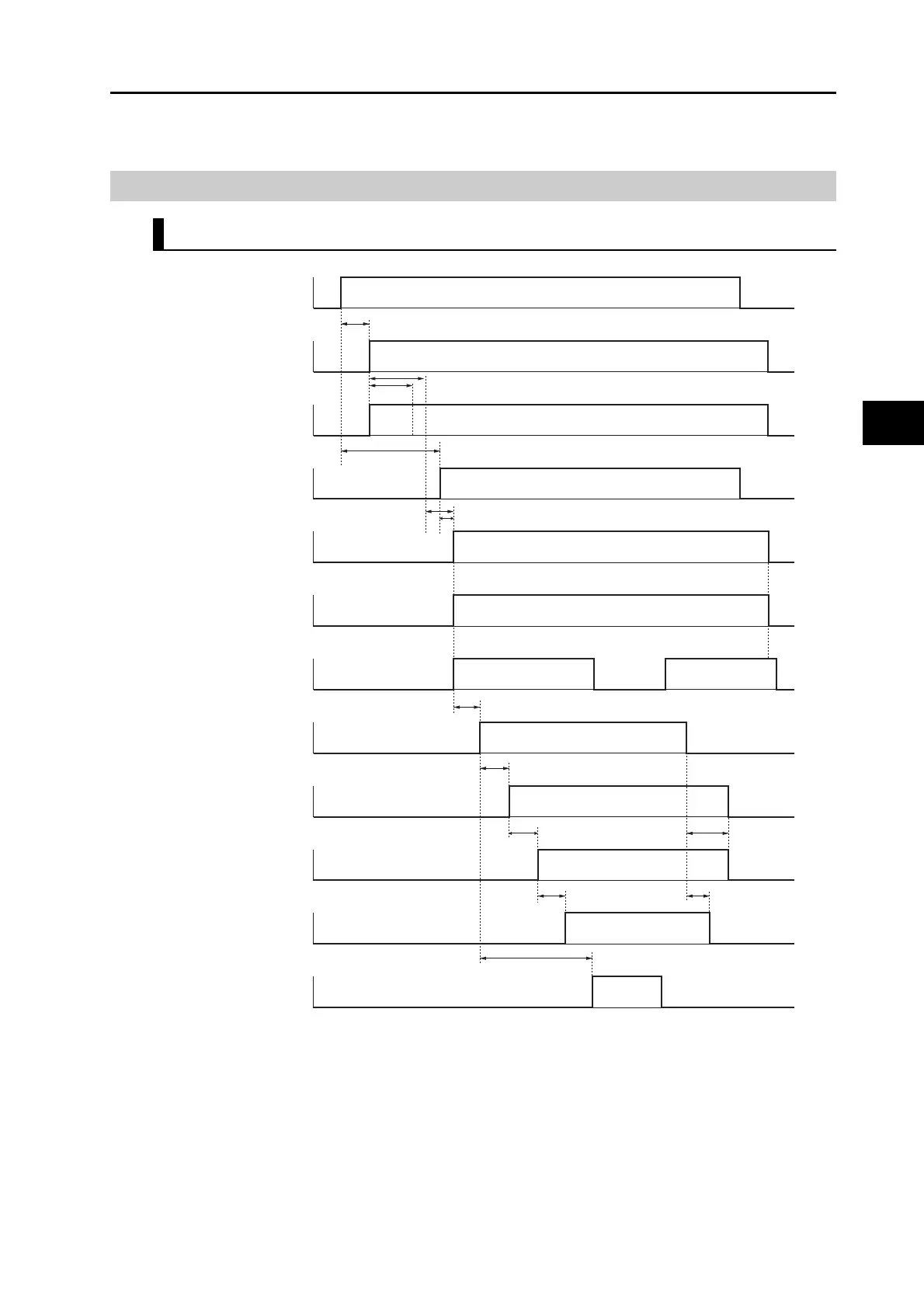
Control Output Details
Control Output Sequence
*1. In this section, the hardware inputs the servo ON signal, but the signal is not accepted.
*2. The servo ready completed output turns ON the moment the conditions of MPU initialization completed and main
circuit power supply establishment are both satisfied.
*3. Once the internal control power is established, the protective function starts working about 1.5 s after the MPU starts
initializing itself. Make sure all I/O signals which connect to the amplifier (especially forward/reverse direction, drive
prohibition input and external encoder input) are established before operation of the protective function starts. Also,
you can increase this time with Pn618 "Power Supply ON Initialization Time."
Control power supply
(L1C and L2C)
Internal control
power supply
MPU initialization
completed
Main circuit power
supply
(L1, L2 and L3)
Servo ready
completed output
(READY)
Alarm output
(/ALM)
Positioning
completion output
(INP)
ON
OFF
ON
OFF
ON
OFF
ON
OFF
ON
OFF
ON
OFF
ON
OFF
Approx. 100 to 300 ms
Approx. 2 s
Approx. 1.5 s
Iinitialization
*3
1 to 6 ms
10 ms after the initialization is completed and the main circuit is turned on
*2
Operation
command input
(RUN)
Dynamic brake
Motor power supply
Brake interlock
output (BKIR)
Servo position, speed,
torque input
ON
OFF
ON
OFF
ON
OFF
ON
OFF
ON
OFF
Approx. 60 ms
Approx. 2 ms
Approx. 4 ms
0 ms or more
0 s or more
100 ms or more
*1
Pn437
 Loading...

