14 Switch Mode Power Supply S82K
Charging the Battery
If a battery is to be connected as the load, install an overcurrent limit-
ing circuit and an overvoltage protection circuit.
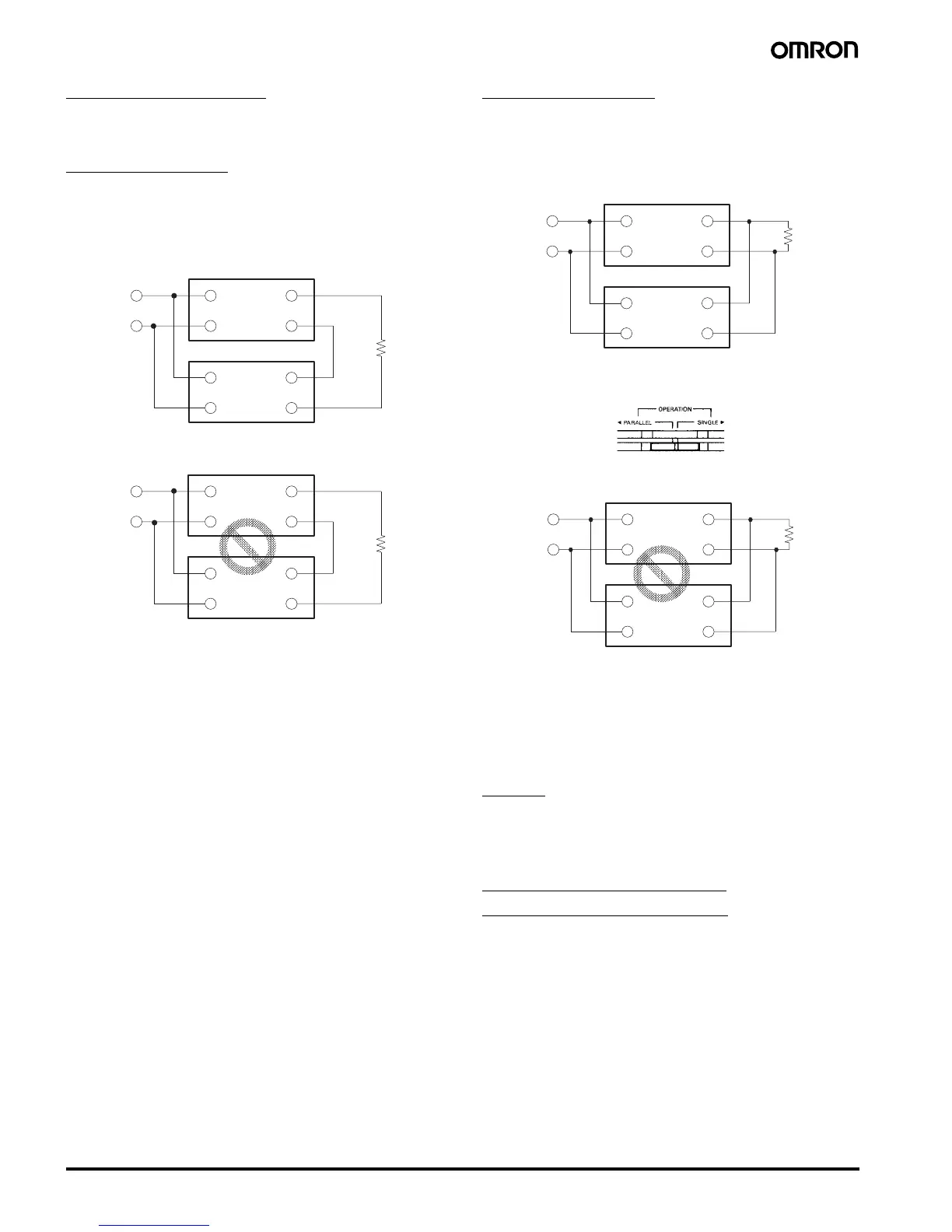
Series Operation
S82K 90-W/100-W models can be operated in series.
It must be noted that the + output of the 7.5-W dual output model
cannot be connected in series to its – output.
Correct
Incorrect
Parallel Operation
S82K 100-W models can be operated in parallel.
Perform parallel operation with power supplies satisfying the same
specifications.
Correct
Note: When operating the S82K-P10024 in parallel operation, set the
switch to “PARALLEL. In this case, the rated current per S82K-
P10024 is 3.78 A.
Incorrect
Parallel Operation Precautions
The length and thickness of each wire connected to the load must be
the same so that there is no difference in voltage drop value between
the load and the output terminals of each Power Supply.
Adjust the output voltage of each Power Supply so that there will be
no difference in output voltage between each Power Supply.
Wiring
Do not apply more than 75-N force to the terminal block when
tightening it.
Ensure that input and output terminals are wired correctly.
Minimum Output Current
(S82K-00727/S82K-00728)
The minimum output current of the S82K-00727 and S82K-00728 is
restricted by the output voltage and control method.
Note: All the outputs of the S82K-00727 and S82K-00728 are
controlled by the +V output. If the +V output current falls to 10%
or less of the rated output, the –V output voltage may drop.
+V
−V
+V
−V
90-, 100-W Models
INPUT
INPUT
+V
−V
+V
−V
3-, 7.5-, 15-, 30-, 50-W Models
INPUT
INPUT
+V
−V
+V
−V
INPUT
INPUT
100-W Models
+V
−V
+V
−V
INPUT
INPUT
3-, 7.5-, 15-, 30-, 50- and 90-W Models
 Loading...