Switch Mode Power Supply S82K 7
Engineering Data
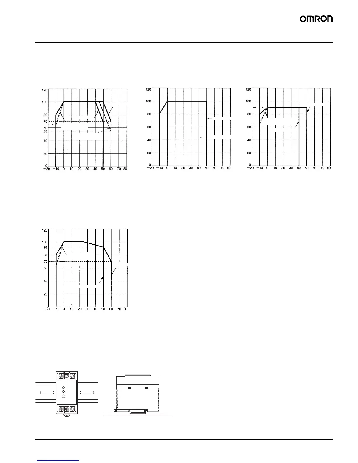
■ Derating Curve (A: Standard mounting, B: Face-up mounting)
■ Mounting
65
65
90
Load (%)
Ambient temperature (°C)
3-/7.5-/15-/30-/50-/100-W
Models
Load (%)
Ambient temperature (°C)
Load (%)
Ambient temperature (°C)
Installation A
Installation A
Installation B
100-W Models with PFC
(S82K-P10024)
Installation B
Parallel-Unit Operation
100-W Models without PFC
(S82K-10024)
Installation A
Installation B
Single-Unit Operation
Parallel-Unit Operation
S82K-P10024:
85-VAC input
S82K-03005
Installation A
Note: When using the 7.5-W single-output
models within the input voltage range
between 90 and 110 VDC, the load
rate will become 90% or less.
S82K-P10024:
85-VAC input
65
90-W Models
Load (%)
Ambient temperature (°C)
Installation A
Installation B
Single-Unit Operation
S82K-P09024:
85-VAC input
Note: 1. Note that the derating curve may vary depending on the installation conditions.
2. Multiple units cannot be installed in a configuration where they are lined up vertically.
3. Use the 7.5-W single-output models under the load of 90% max. if the voltage range is between 90 and 110 VDC.
4. The cold-start time will be longer when using S82K-P09024 or S82K-P10024 with 85-VAC input.
(A) Standard mounting (B) Face-up mounting
Top Top
Note: Installations other than (A) and (B) are not possible.
 Loading...