8 Switch Mode Power Supply S82K
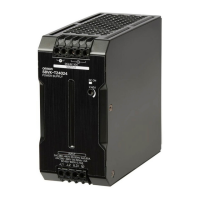
■ Overload Protection
The Power Supply is provided with an overload protection function that protects the Power Supply from possible damage by overcurrent. When the
output current rises above 105% min. of the rated current, the protection function is triggered, automatically decreasing the output voltage. When
the output current falls within the rated range, the overload protection function is automatically cleared.
Note: 1. When connecting a load that has a built-in DC-DC converter, the overcurrent protection function may operate during start-up, thus pre-
venting the Power Supply from starting.
2. Internal parts may occasionally deteriorate or be damaged if a short-circuited or other overcurrent state continues during operation.
3. When using the 7.5-W single-output models within the input voltage range between 90 and 110 VDC, the overload protection function
will operate at currents from 95% to 160% of the rated output current.
4. When using the 90-W model at an ambient temperature of 25
°C or less, the overload protection function will operate at currents from
101% to 111% of the rated output current. When using the 90-W model at an ambient temperature exceeding 25
°C, the overload protec-
tion function will operate at currents from 92% to 111% of the rated output current.
5. When using the 100-W model with PFC in parallel operation, operation is limited to a load ratio of 90% to 100% of the rated output current
at 4.2 A.
When Using ± Output Models
The +V output detects the total output power (+V output and −V output) to trigger the short-circuit protection against overcurrent. This protection
varies depending on the
−V output state. The −V output independently triggers the short-circuit protection.
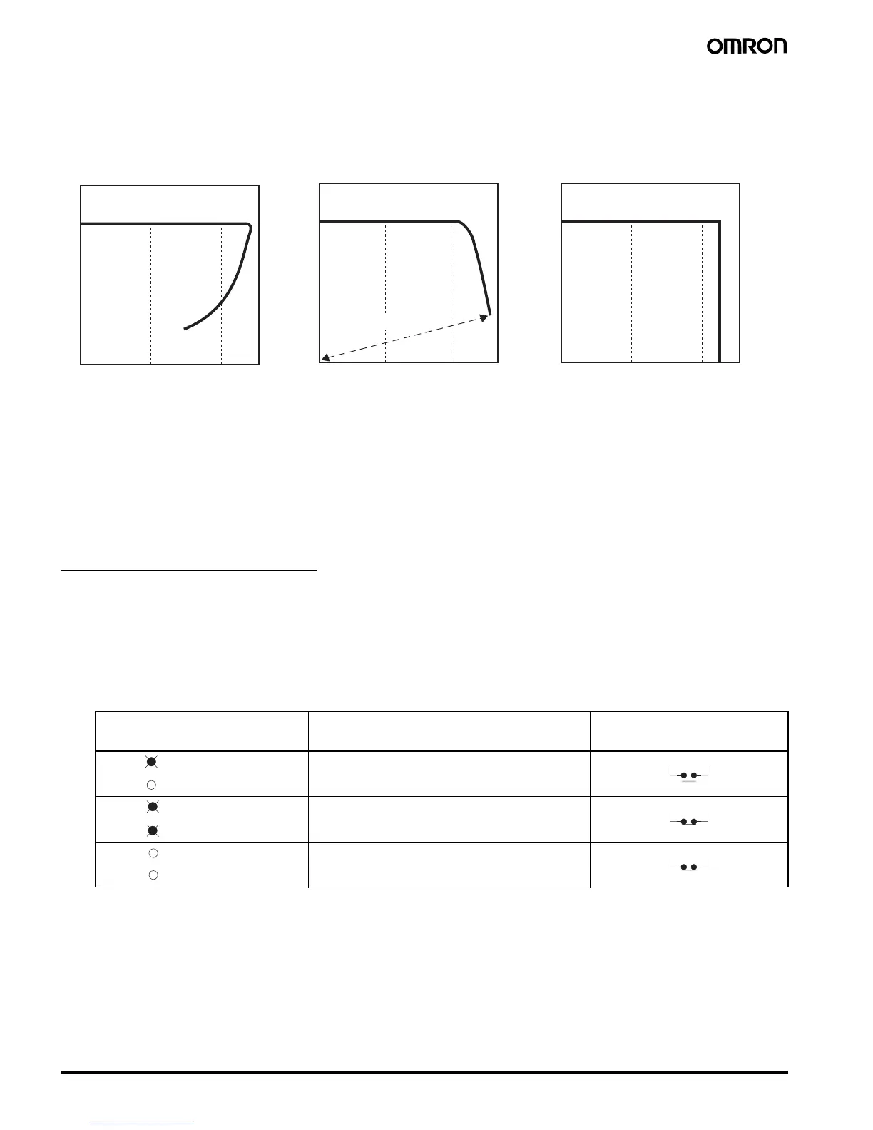
■ Undervoltage Alarm Indicator and Output Function
If the output voltage at the output terminal drops to 75% to 90% of the rated voltage, the red indicator of the S82K (DC LOW indicator) will be lit.
In the case of the S82K-@09024/@10024, a voltage drop alarm will be output via the relay available in the models (DC LOW output).
Note: This function detects the voltage at the output terminal of the Power Supply. To check the precise output voltage, measure the voltage at the
terminal of the load.
Note: 1. The more the voltage at the output terminal drops, the darker both the green and red indicators will be.
2. The relay contacts have a capacity of 0.1 A at 24 VDC.
3. The red indicator will actually first light at a voltage between 75% and 90% of the rated voltage.
Out
Output voltage (V)
90-/100 W Models
Indicator Voltage Operation of @09024/@10024’s
output (DC LOW output)
(See note 2.)
If the voltage at the output terminal is more than 82% of
the rated voltage and operation is normal, the green in-
dicator will be lit and the red indicator will not be lit.
If the voltage at the output terminal drops to below 82%
of the rated voltage, the red indicator will be lit. (See
note 3.)
If the voltage at the output terminal approaches 0 V,
both the green and red indicators will not be lit.
Green: DC ON
Red: DC LOW
Green: DC ON
Red: DC LOW
(See note 1.)
Green: DC ON
Red: DC LOW
 Loading...