3
Input/output assignments
8
■
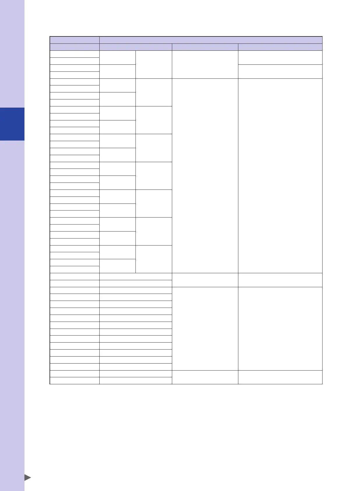
Output from the host control device, input to the controller
Host control device Controller
Address (WRITE) Address (READ) Input/output type Use
Q m
SIW(0)
- Word input
Remote command area
Q m+1
Q m+2
SIW(1) Command data area
Q m+3
Q m+4
SIW(2)
SID(2)
Word input /
Double word input
Command data area /
General-purpose input area
Q m+5
Q m+6
SIW(3)
Q m+7
Q m+8
SIW(4)
SID(4)
Q m+9
Q m+10
SIW(5)
Q m+11
Q m+12
SIW(6)
SID(6)
Q m+13
Q m+14
SIW(7)
Q m+15
Q m+16
SIW(8)
SID(8)
Q m+17
Q m+18
SIW(9)
Q m+19
Q m+20
SIW(10)
SID(10)
Q m+21
Q m+22
SIW(11)
Q m+23
Q m+24
SIW(12)
SID(12)
Q m+25
Q m+26
SIW(13)
Q m+27
Q m+28
SIW(14)
SID(14)
Q m+29
Q m+30
SIW(15)
Q m+31
Q m+32 SI07 - SI00
Bit input Command input area
Q m+33 SI17 - SI10
Q m+34 SI27 - SI20
But input /
Byte input
General-purpose input area
Q m+35 SI37 - SI30
Q m+36 SI47 - SI40
Q m+37 SI57 - SI50
Q m+38 SI67 - SI60
Q m+39 SI77 - SI70
Q m+40 SI107 - SI100
Q m+41 SI117 - SI110
Q m+42 SI127 - SI120
Q m+43 SI137 - SI130
Q m+44 SI147 - SI140
Q m+45 SI157 - SI150
Q m+46 (Reserve)
Reserved area Use is prohibited
Q m+47 (Reserve)
Q(m) : Starting address of the output data area for the target controller
• Q(m), Q(m+1), ..., Q(m+47) assume data memory that is divided at each byte (8-bits).
• SIx() is handled as unsigned 8-bit integer data. (x=2-7, 10-17)
• SIW(y) is handled as unsigned 16-bit integer data. (y=0 - 15)
• The upper byte and lower byte of SIW(y) correspond to Q(2y+1) and Q(2y) respectively.
• SID(z) is handled as signed 32-bit integer data. (z=2, 4, ..., 14)
• The upper word and lower word of SID(z) correspond to SIW(z+1) and SIW(n), respectively.
* For details on the functions that are assigned to each serial input/output data, refer to the separate Remote
I/O Manual.
* The reserved area cannot be used.
 Loading...