3-15
thermal relay to detect resistor overheating. When using a Braking Resistor Unit,
use an error output contact. Otherwise, a fire may occur.
3G3EV Model Braking Resistor
(Duty Cycle 3%ED)
Braking Resistor
Unit
(Duty Cycle 10%ED)
Minimum
connected
resistance
A2001M(-j)/AB001M(-j)
3G3IV-PERF150WJ401
---
200 Ω
A2002M(-j)/AB002M(-j)
(400 Ω)
200 Ω
A2004M(-j)/AB004M(-j)
3G3IV-PERF150WJ201
3G3IV-PLKEB20P7
200 Ω
A2007M(-j)/AB007M(-j)
(200 Ω) (200 Ω 70 W)
80 Ω
A2015M(-j)/AB015M(-j)
3G3IV-PERF150WJ101
(100 Ω)
3G3IV-PLKEB21P5
(100 Ω 260 W)
60 Ω
A4002M(-j)/A4004M(-j)
3G3IV-PERF150WJ751
3G3IV-PLKEB40P7
750 Ω
A4007M(-j)
(750 Ω) (750 Ω 70 W)
510 Ω
A4015M(-j)
3G3IV-PERF150WJ401
(400 Ω)
3G3IV-PLKEB41P5
(400 Ω 260 W)
240 Ω
Note Do not use a Resistor whose resistance is below the minimum connected resis-
tance. Otherwise, the Inverter will be damaged.
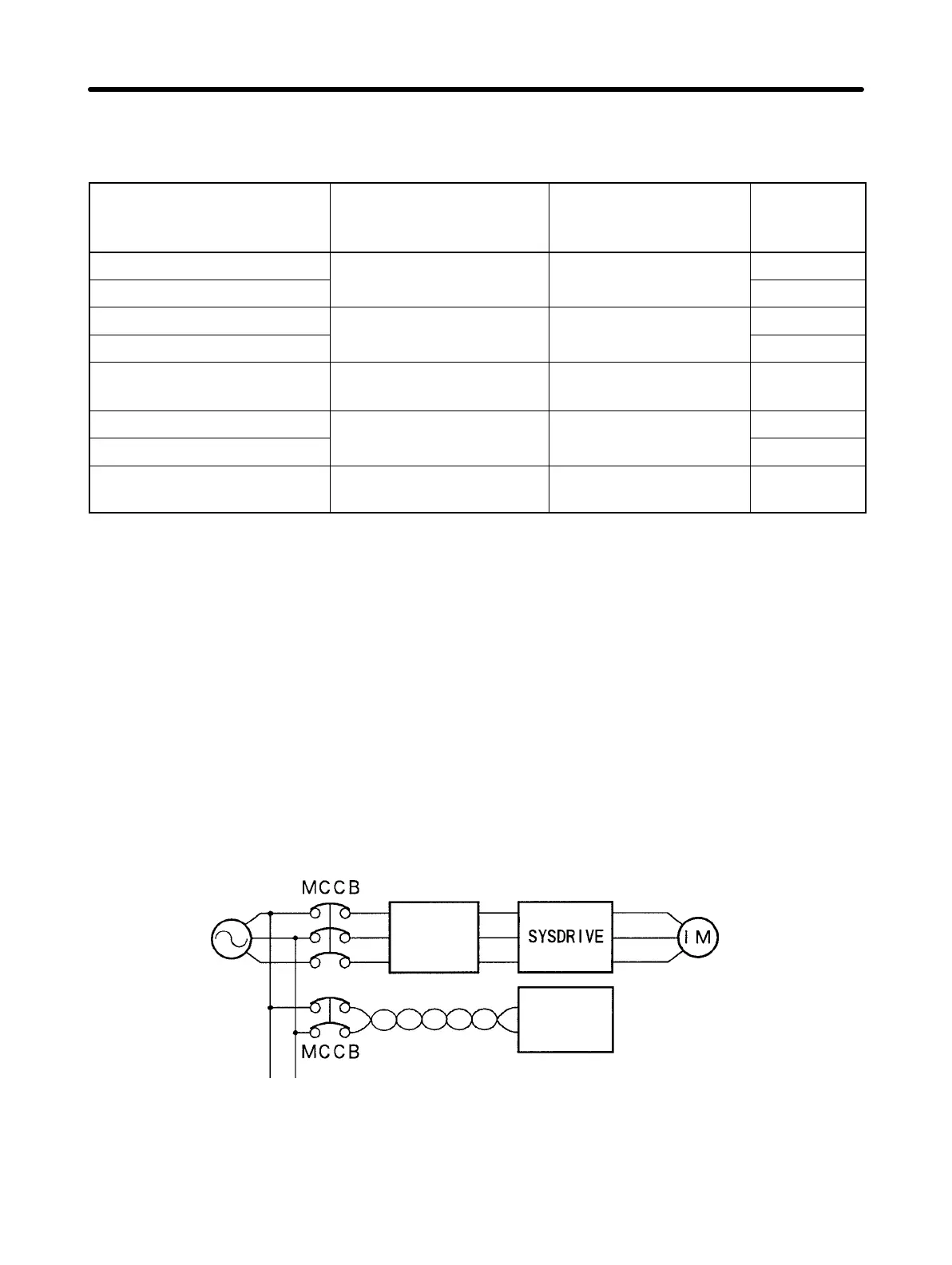
D Installing a Noise Filter on the Power Supply Side
Install a noise filter to eliminate noise transmitted between the power line and the
Inverter.
Wiring Example
Input Noise Filters
Simple Input Noise Filter: 3G3EV-PLNFj
EMC-conforming Input Noise Filter: 3G3EV-PNFj
3G3EV
Power
supply
Noise
filter
SYSMAC,
etc.
Other controllers
Note Use a noise filter designed for Inverters. A general-purpose noise filter will be less
effective and may not reduce noise.
Design Chapter 3