3-20
D Wiring Method
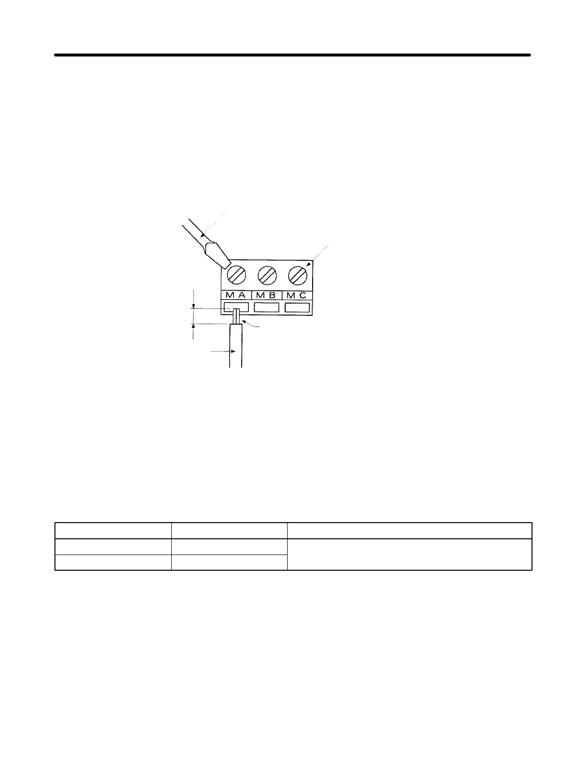
•Wire each terminal as follows:
a) Loosen the terminal screw with a thin-slotted screwdriver.
b) Insert the wire from underneath the terminal block.
c) Tighten the terminal screw firmly.
•Always separate the control signal line from the main circuit cables and other power
cables.
Thin-slotted screwdriver
Length of
stripped portion:
Approx. 5.5 mm
Wire
Control circuit
terminal block
Do not solder this portion.
(Otherwise, faulty contact may result.)
H Wiring Frequency Reference Input Terminals
If frequency references are input using a D/A Unit (digital-to-analog converter) or exter-
nal power supply, wire the frequency reference input terminals (FR and FC) as de-
scribed below.
D Wires to be Used
Always use twisted-pair shielded wires to prevent malfunctions due to noise.
Wire type Wire size Wire to be used
Single wire 0.5 to 1.25 mm
2
Polyethylene-insulated cable for
Stranded wire 0.5 to 1.25 mm
2
instrumentation (with shield)
Design Chapter 3