4-6
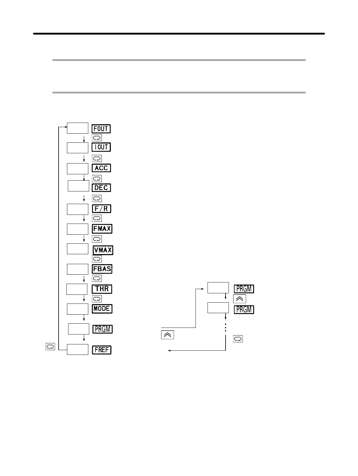
H Switching Data Display when Inverter is Stopped
Press the Mode Key to switch data display.
When the Inverter is stopped, all items can be monitored and the constant
for each item can be set.
Example
of data
display
Indi-
cator
Description
Output frequency
monitoring (Hz)
Output current monitoring
(effective current: A)
Acceleration time
(seconds)
Deceleration time
(seconds)
Forward/Reverse rotation selection
f%r: Forward rotation reU: Reverse rotation
Maximum frequency (Hz)
Maximum voltage (V)
Maximum voltage
frequency (Hz)
Electronic thermal
reference current (A)
Operation
mode selection
Constant no.
Reference
frequency (Hz)
Note The indicators displayed
when the power is
turned on are the same
as shown in the previous
section “Switching Data
Display during Opera-
tion.”
60.0
10.0
0.6
10.0
f%r
60.0
200
0
n01
60.0
n02
n03
0.0
0.0
Example
of date
display Indicator
Preparing for Operation Chapter 4