4-35
n56 to
n58
Jump Frequencies 1 to 3
Setting range 0.0 to 400 (Hz) Factory setting 0.0 (Hz)
Unit of setting 0.0 to 99.9 (Hz) : 0.1 (Hz)
100 to 400 (Hz) : 1 (Hz)
n59
Jump Width
Setting range 0.0 to 25.5 (Hz) Factory setting 1.0 (Hz)
Unit of setting 0.1 (Hz)
•These constants are used to change the output frequency to prevent the resonance of
the mechanical system connected to the Inverter.
•These constants are used effectively to create the dead band of a frequency reference.
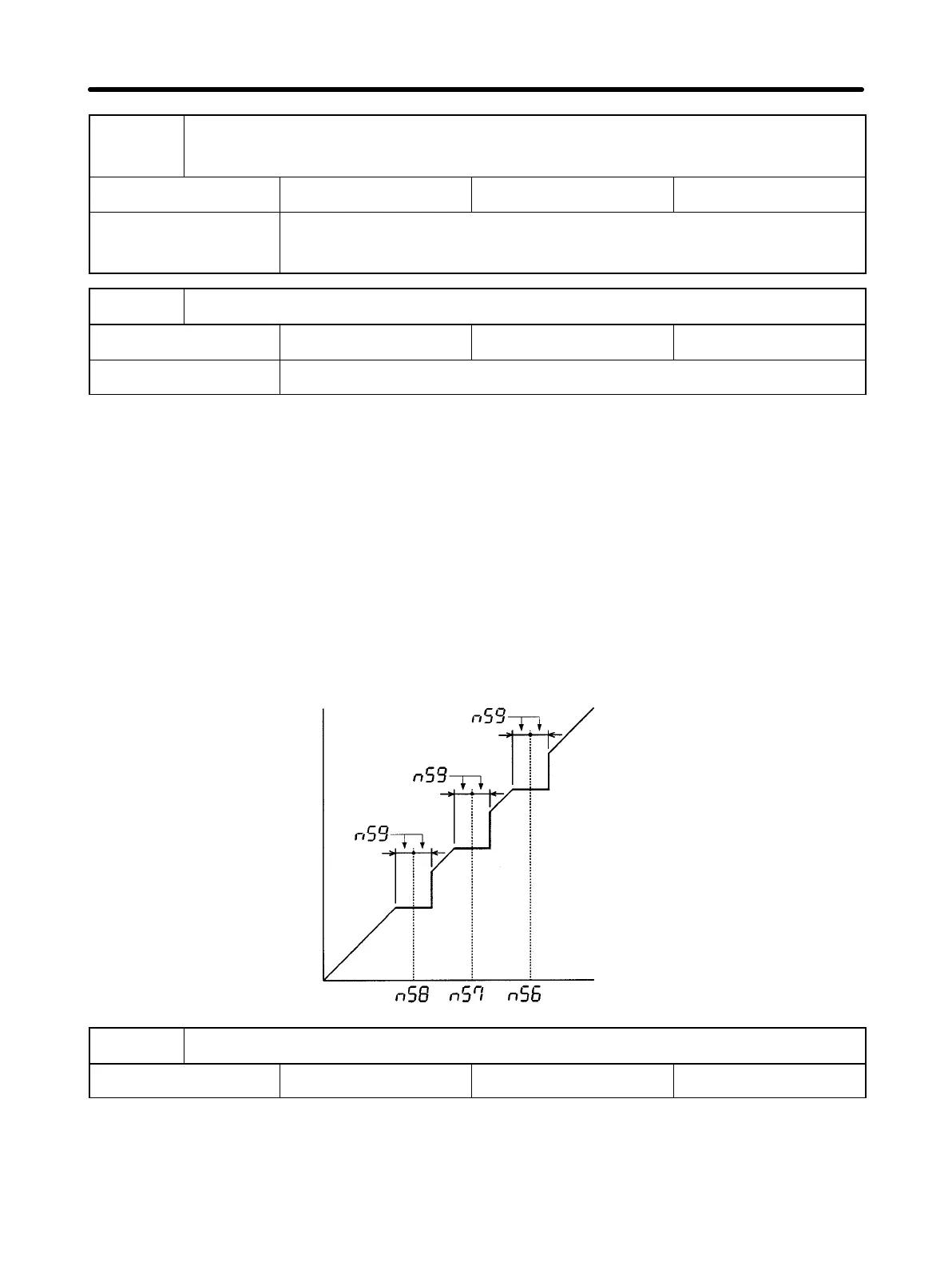
•Set the constants in n56 to n58 for the central values of jumping frequencies.
These constants must satisfy the following condition, otherwise an error will result:
n56 ≥ n57 ≥ n58
•The constant in n59 must be set for the jump width value so that the middle values of
the jump widths will be the central values of the required jumping frequencies.
Example of Frequency Jump Function
Reference frequency
Output frequency
n60
Number of Fault Retries
Setting range 0 to 10 (times) Factory setting 0 (times)
CautionThe Inverter may be damaged if the fault retry function is used.
Protect the Inverter as described below before using the fault retry function:
Preparing for Operation Chapter 4