5-3
H Data Display and Action to be Taken when Warning Status
Arises
The ALARM indicator flashes when warning status arises. The data display section also
flashes.
When warning status arises, no error code is output.
Eliminating the cause recovers the system automatically.
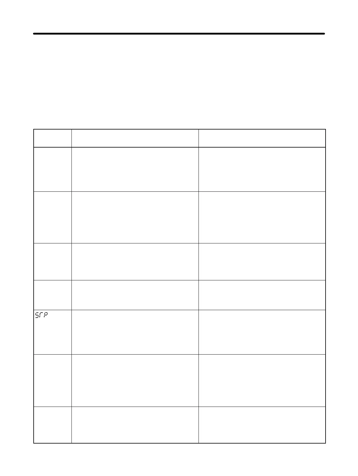
Data
display
Description Action
ef
flashing
Simultaneous input of forward and
reverse rotation commands
Forward and reverse rotation
commands were simultaneously input
for 0.5 second or more.
•Review the sequence.
uU
flashing
Main circuit undervoltage (UV)
The DC voltage of the main circuit
dropped below the low-voltage
detection level when the Inverter was
stopped.
•Check the power voltage.
•Check the power input line for discon-
nection.
•Check the terminal block screws for
looseness.
%U
flashing
Main circuit overvoltage (OV)
The DC voltage of the main circuit
exceeded the overvoltage detection
level when the Inverter was stopped.
•Check the power voltage.
%h
flashing
Radiation fin overheated (OH)
The radiation fin overheated when the
Inverter was stopped.
•Check the ambient temperature.
•Install a cooling fan or air conditioner.
flashing
(see note)
Digital Operator stopped (STP)
The STOP/RESET Key on the Digital
Operator was pressed while the
Inverter was being operated using
control circuit terminals SF and SR.
•Open both SF and SR.
%l3
flashing
Over-torque (OL3)
The flow of current exceeded the
value determined with the constant
set in n51 for more than the specified
period determined with the constant
set in n52.
•Make sure that the n51 and n52 set-
tings are appropriate.
•Check the operating status of the me-
chanical system and remove the
cause of the error.
bb
flashing
External base block in progress
(bb)
An external base block signal was
input.
•Make sure that the sequence circuit is
appropriate.
Operation Chapter 5