603
K3T
@
Intelligent Signal Processor Protocol Appendix L
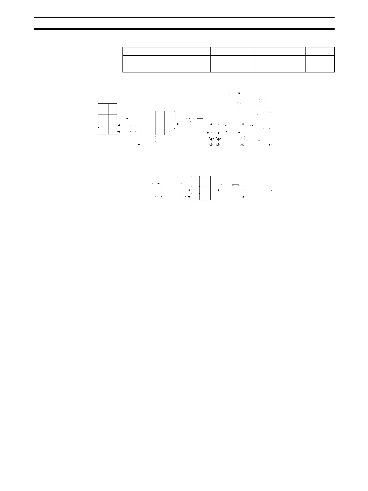
• RS-485 2-wire Connections
Note 1. The connection configuration is a one-to-one or a 1-to-N configuration. For 1-to-N connections, up to
32 units including the Serial Communications Boards/Units can be connected.
2. The maximum cable length is 500 m. Use shielded twisted-pair cables (AWG28i or greater).
3. Connect terminating resistance at both ends of the transmission path.
4. Turn the terminal block switch ON at the terminators.
5. Turn the terminal block switches OFF for units that are not terminators.
Signal name Abbreviation Signal direction Terminal
Inverting output – Input or output 19
Non-inverting output + Input or output 18
Serial Communications
Board/Unit
Shield
Intelligent Signal Processor
Turn ON the terminal block switch for
terminators only.
Signal
Name
Pin
No.
SN751177N or
equivalent
Shield
Signal
Name
Signal
Name
Intelligent Signal Processor
Unit designated as terminator.
The terminal block switch is turned ON.
Terminal
block SW
Terminal block SW ON
Te r mi -
nal.
Te r mi -
nal.
RS-485: D-sub
9-pin female
RS-485:
Terminal block
SDA
SDB
*1: Set the 2-/4-wire switch
to the 2-wire setting.
*2: Turn ON the terminat-
ing resistance switch.
FG
1
2
19
18
18
19
220 Ω
220 Ω
4.7 kΩ
4.7 kΩ
4.7 kΩ
6.8 V
5 V
51 kΩ
TX
RX
RS-485:
Terminal block
 Loading...


