5-21
5 I/O Memory
CP2E CPU Unit Software User’s Manual(W614)
5-9 Data Registers (DR)
5
5-9 Data Registers (DR)
The sixteen Data Registers (DR0 to DR15) are used to offset the PLC memory addresses in Index Reg-
isters when addressing words indirectly. The Data Registers can be used to specify an offset to add to
an Index Register when addressing words indirectly.
The content of Data Registers cannot be accessed (read or written) from the CX-Programmer.
Index register numbers range from DR0 to DR15.
z Forcing Bit Status
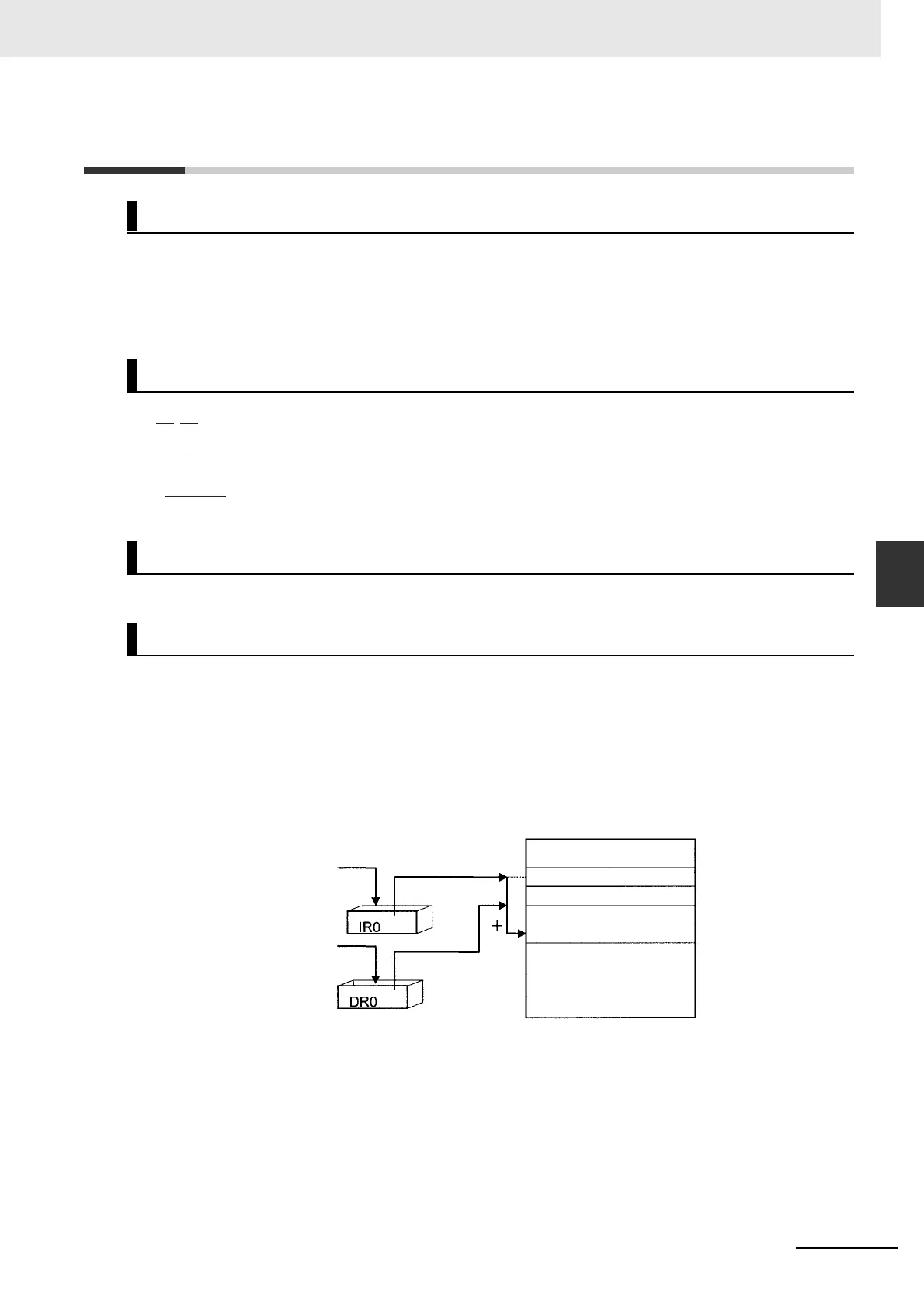
The value in a Data Register can be added to the PLC memory address in an Index Register to
specify the absolute memory address of a bit or word in I/O memory. Data Registers contain signed
binary data, so the content of an Index Register can be offset to a lower or higher address.
Normal instructions can be use to store data in Data Registers.
Data Registers cannot be force-set or force-reset.
Example
The following examples show how Data Registers are used to offset the PLC memory addresses in
Index Registers.
LD DR0 ,IR0 Adds the contents of DR0 to the contents of IR0 and
loads the bit at that PLC memory address.
MOV #0001 DR0 ,IR1 Adds the contents of DR0 to the contents of IR1 and
writes #0001 to that PLC memory address.
Overview
Notation
Range
Details
DR
Index register number: 13
Index register designator: DR
13
Set to a base value
with MOVR(560) or
MOVRW(561).
Set with a regular
instruction.
Pointer
I/O Memory