17 Analog Input/Output Option Board
17-6
CP2E CPU Unit Software User’s Manual(W614)
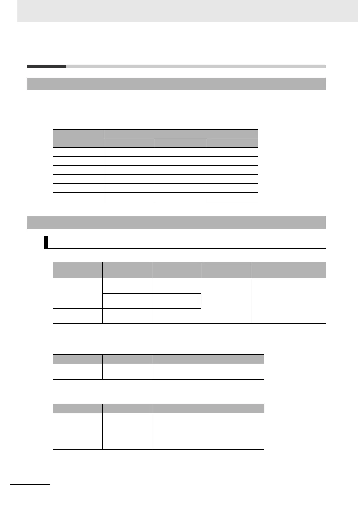
17-4 Memory Allocation
The memory allocation about analog conversion in the CIO area of PLC is shown as the following diagram.
The range of the CIO area is CIO80 to CIO89.
The details of allocated CIO channels are described in the following table.
Option board status area: A435 (initial value “0000H”)
Note The flag sets ON if Analog Option Board has already worked normally. Then A/D input data can be read and
D/A output data can be written.
Output off bit: A500.15
Note This bit will also affect other PLC output channels.
Option board error bit: A315.13
17-4-1 CIO Area Allocation
Channel
Contents
CP1W-ADB21 CP1W-DAB21V CP1W-MAB221
CIO80 Analog Input 1 --- Analog Input 1
CIO81 Analog Input 2 --- Analog Input 2
CIO82 to CIO84 --- --- ---
CIO85 --- Analog Output 1 Analog Output 1
CIO86 --- Analog Output 2 Analog Output 2
CIO87 to CIO89 --- --- ---
17-4-2 Auxiliary Area Allocation
Analog Option Unit Status Area
CPU Unit
Option board
slot
AR bits Content Error Process
CP2E
N30/N40/N60
CPU Unit
Option board slot
1 (left)
A435.14 I/O option board
run state
0: Initial state or unit abnor-
mal state
1: Work normally
Option board slot
2 (right)
A435.15
CP2E N14/N20
CPU Unit
Option board slot A435.14
AR Bits Content Error Process
A500.15 Output Off Bit 0: Output effective
1: Analog option board DA output clear
AR Bits Content Error Process
A315.13 Option board error
bit
• Turn ON when two Analog Option Boards
are installed on CP2E N30/40/60 CPU
Unit.
• Cleared when the corresponding anomaly
is cleared.