12-45
12 Pulse Outputs
CP2E CPU Unit Software User’s Manual(W614)
12-8 Related Auxiliary Area Flags
12
12-8 Related Auxiliary Area Flags
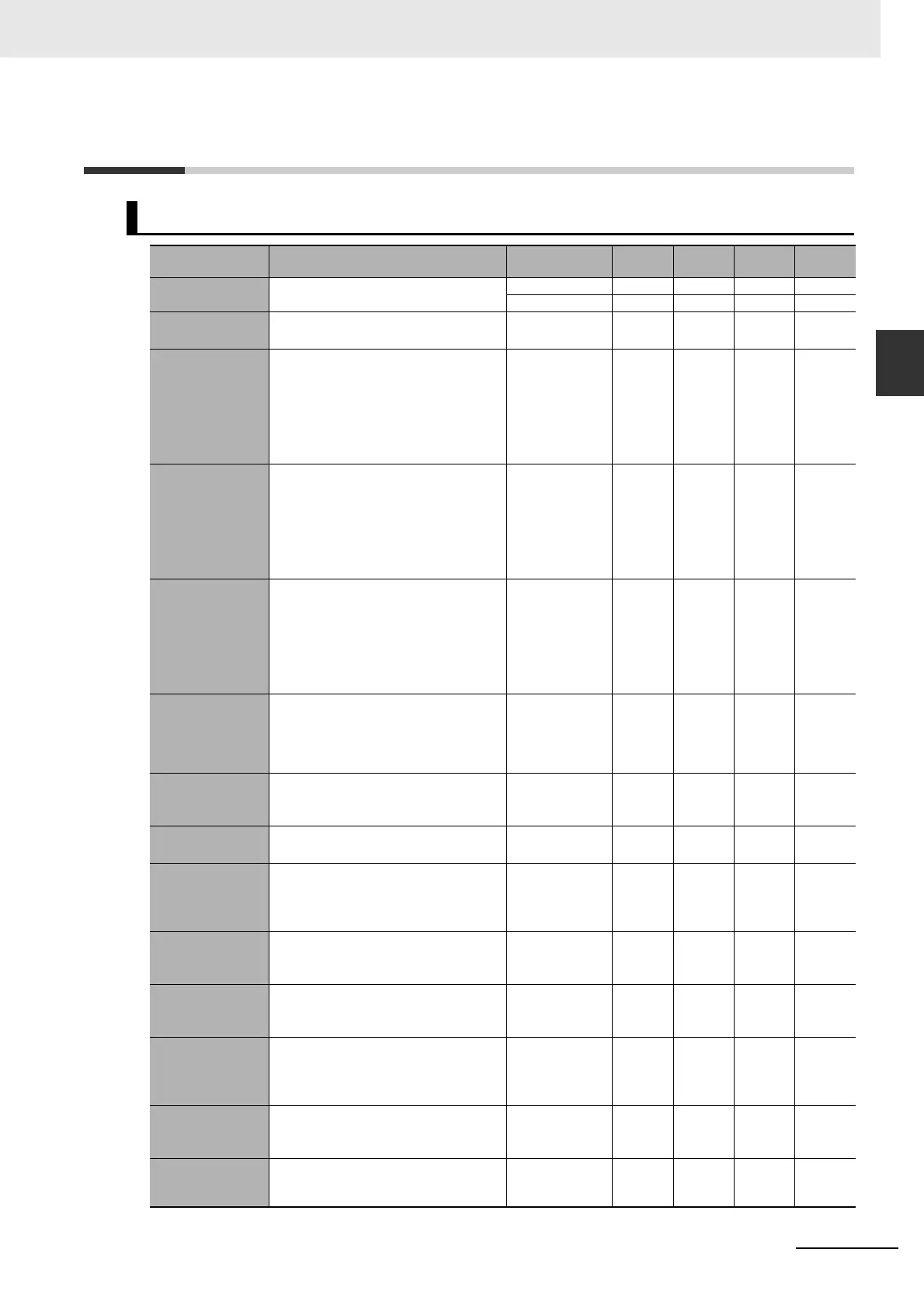
Auxiliary Area Allocations
Name Description Values
Pulse
output 0
Pulse
output 1
Pulse
output 2
Pulse
output 3
Pulse Output PV
Storage Words
PV range: 8000 0000 to 7FFF FFFF hex
(-2,147,483,648 to 2,147,483,647)
Leftmost 4 digits A277 A279 A53 A55
Rightmost 4 digits A276 A278 A52 A54
Pulse Output
Reset Bit
The pulse output PV will be cleared when
this bit is turned ON.
0: Not cleared.
1: Clear PV.
A540.00 A541.00 A542.00 A543.00
CW Limit Input
Signal Flag
This flag shows the status of the CW Limit
Input Signal, which is used in the origin
search.
The status of the signal from the CW limit
input sensor connected to a normal input
must be written to A540.08, A541.08,
A542.08 or A543.08.
ON when turned
ON from an
external input.
A540.08 A541.08 A542.08 A543.08
CCW Limit Input
Signal Flag
This flag shows the status of the CCW
Limit Input Signal, which is used in the ori-
gin search.
The status of the signal from the CCW
limit input sensor connected to a normal
input must be written to A540.09,
A541.09, A542.09 or A543.09.
ON when turned
ON from an
external input.
A540.09 A541.09 A542.09 A543.09
Positioning
completed input
signal
This flag shows the status of the position-
ing completed input signal, which is used
in the origin search.
The status of the Positioning Completed
Signal from the Servo Drive connected to
a normal input must be written to
A540.10, A541.10, A542.10 or A543.10.
ON when turned
ON from an
external input.
A540.10 A541.10 A542.10 A543.10
Accel/Decel Flag ON when pulses are being output accord-
ing to an ORG, ACC, PLS2, IFEED or
ITPL instruction and the output frequency
is being changed in steps (accelerating or
decelerating).
0: Constant
speed
1: Accelerating or
decelerating
A280.00 A281.00 A56.00 A57.00
Overflow/Underflow
Flag
ON when an overflow or underflow has
occurred in the pulse output PV.
0: Normal
1: Overflow or
underflow
A280.01 A281.01 A56.01 A57.01
Output Amount Set
Flag
ON when the number of output pulses has
been set with the PULS instruction.
0: No setting
1: Setting made
A280.02 A281.02 A56.02 A57.02
Output Completed
Flag
ON when the number of output pulses set
with the PULS, PLS2, IFEED or ITPL
instruction has been output.
0: Output not
completed.
1: Output
completed.
A280.03 A281.03 A56.03 A57.03
Output In-progress
Flag
ON when pulses are being output from the
pulse output.
0: Stopped
1: Outputting
pulses.
A280.04 A281.04 A56.04 A57.04
No-origin Flag ON when the origin has not been defined
for the pulse output.
0: Origin defined.
1: Origin
undefined.
A280.05 A281.05 A56.05 A57.05
At-origin Flag ON when the pulse output PV matches
the origin (0).
0: Not stopped at
origin.
1: Stopped at
origin.
A280.06 A281.06 A56.06 A57.06
Output Stopped
Error Flag
ON when an error occurred while output-
ting pulses in the origin search function.
0: No error
1: Stop error
occurred.
A280.07 A281.07 A56.07 A57.07
Stop Error Code When a Pulse Output Stop Error occurs,
the error code is stored in that pulse out-
puts corresponding Stop Error Code word.
− A444 A445 A438 A439