9 Quick-response Inputs
9-4
CP2E CPU Unit Software User’s Manual(W614)
Note 1 The power supply must be restarted after the PLC Setup is transferred in order to validate the quick-
response input settings.
2 IN8 and IN9 are only supported by N20/30/40/60 CPU Units.
The following terminals can be used for quick-response inputs.
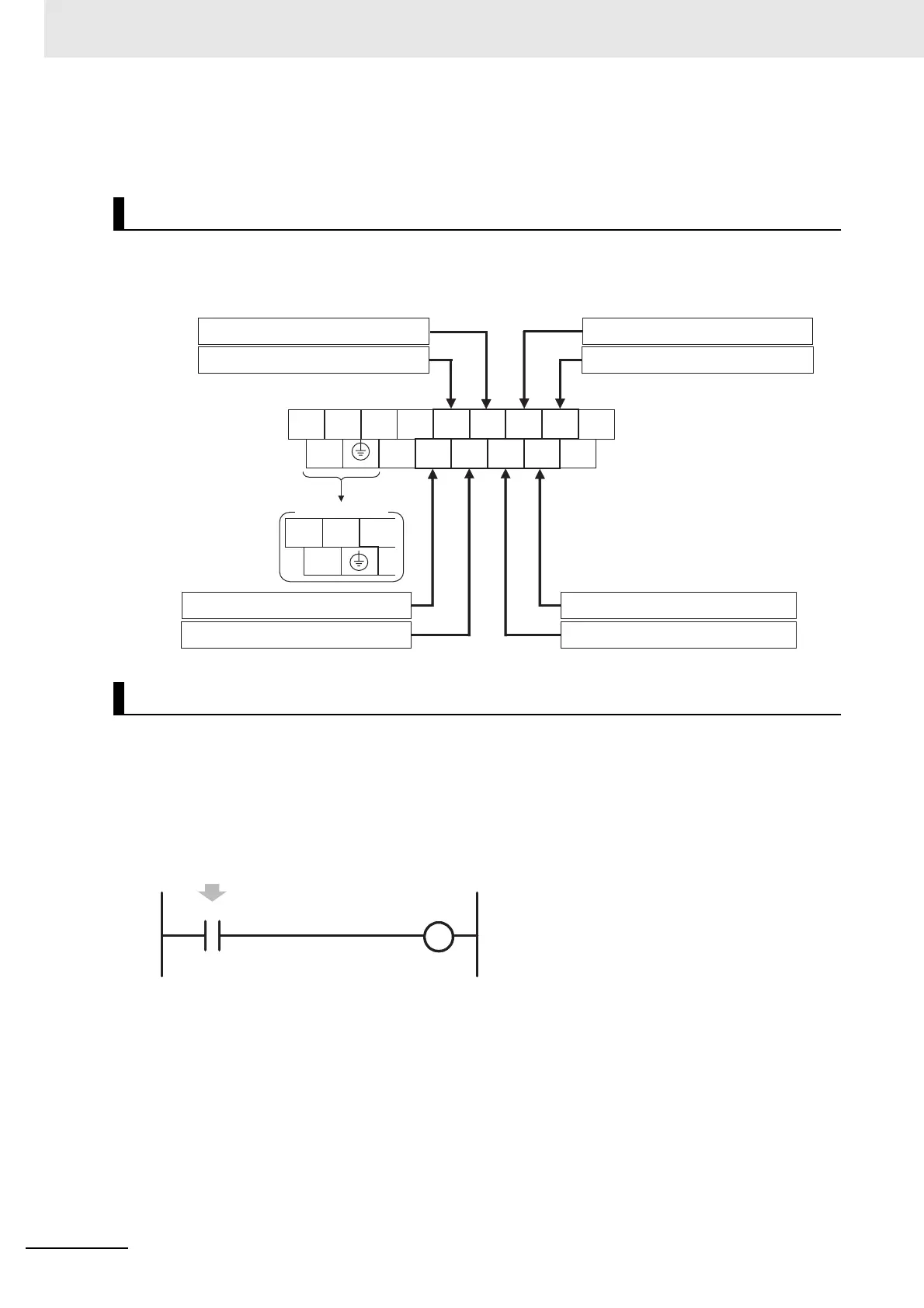
z Input Terminal Block on CPU Unit with 20 I/O Points
Pulse inputs shorter than the cycle time can be read in the CPU Unit I/O memory using normal instruc-
tions. Simply set the interrupt setting for the required input to Quick in the PLC Setup.
The status of CIO 0.02 to CIO 0.09 can be read using instructions such as the LD instruction.
Example: Setting IN2 to Quick in the PLC Setup Interrupt Settings.
• The minimum pulse width (ON time) that can be read for a quick-response input is 50 µs.
• The status of the input that is stored in the I/O memory for a short input will be cleared during the next
I/O refresh period.
Quick-response Input Terminal
Creating Ladder Programs
L1 L2/N COM 01 03 05 07 09 11
NC 00 02 04 06 08 10
Upper Terminal Block
Quick-response input IN5: CIO 0.05
Quick-response input IN3: CIO 0.03
Quick-response input IN9: CIO 0.09
Quick-response input IN7: CIO 0.07
Quick-response input IN6: CIO 0.06
Quick-response input IN2: CIO 0.02
Quick-response input IN8:CIO 0.08
Quick-response input IN4: CIO 0.04
CIO 0
COM
+
-
NC
DC Power Supply
0.02
Even if the signal that is input to terminal 02 on terminal block
0CH is shorter than the cycle time, the signal will be latched in
one cycle and the status will be stored in CIO 0.02.