4-29
4 Understanding Programming
CP2E CPU Unit Software User’s Manual(W614)
4-6 Index Registers
4
4-6-2 Using Index Registers
The data in D0 to D99 (augend data) is added to the data in D100 to D199 (addend data) and the addi-
tion results are output to D200 to D299. The operands of a single addition instruction are specified by
index registers and the addition operations are performed by incrementing the index registers and
repeatedly executing the addition instruction.
Additional Information
Index Registers can be directly addressed only in the instructions shown in the following table.
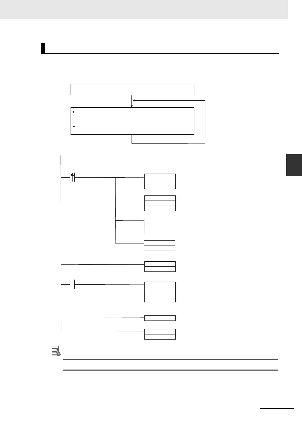
Application Example for Index Registers
MOVR
D0
IR0
a
MOVR
D100
IR1
MOVR
D200
IR2
FOR
&100
+
,IR0+
,IR1+
,IR2+
a
NEXT
JME
&50
JMP
&50
MOVR(560) sets the PLC memory addresses of D0, D100, and D200 in
index registers IR0, IR1, and IR2.
The augend data (indirectly addressed by IR0+) is added to the addend
data (indirectly addressed by IR1+) with the SIGNED BINARY ADD
WITHOUT CARRY instruction (+(400)) and the result is output to the word
indirectly addressed by IR2+.
Index registers IR0+, IR1+, and IR2+ are automatically incremented after
being referenced in the +(400) instruction.
Repeated 100 times.
When execution condition “a” goes ON
(upwardly differentiated condition), the
PLC memory addresses of D0, D100,
and D200 are set in index registers IR0,
IR1, and IR2.
The following FOR-NEXT loop is not
executed unless execution condition “a”
is upwardly differentiated (OFF→ON).
Start loop.
If execution condition “a” is ON, the
word indirectly addressed by IR0
(auto-incremented) and the word
indirectly addressed by IR1
(auto-incremented) are added as 4-digit
signed hexadecimal values and the
result is output to the w
ord indirectly
a
ddressed by IR2 (auto-incremented).
Return to FOR and repeat loop.
Jump destination when execution
condition “a” is not upwardly
differentiated (OFF→ON).
Execution condition
Execution condition