10 Frequency inverters
Main circuit
Control Circuit
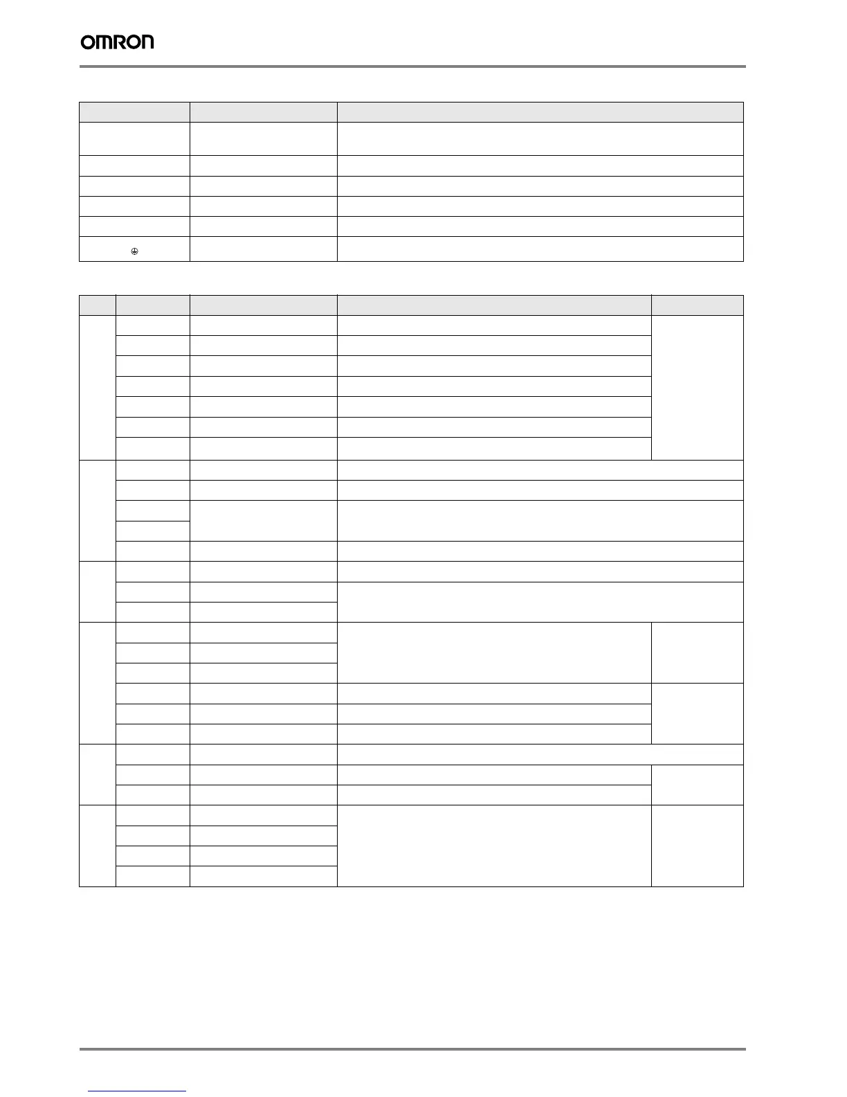
Terminal Name Function (signal level)
R/L1, S/L2, T/L3
Main circuit power supply input Used to connect line power to the drive.
Drives with single-phase 200 V input power use only terminals R/L1 and S/L2
(T/L3 is not connected to anything)
U/T1, V/T2, W/T3
Inverter output Used to connect the motor
B1, B2
Braking resistor connection Available for connecting a braking resistor or the braking resistor unit option.
+2, +1
DC reactor connection Remove the short bar between +2 and +1 when connecting DC reactor (option)
+1, –
DC power supply input For power supply input (+1: positive electrode; – : negative electrode)*
Grounding For grounding (grounding should conform to the local grounding code.)
Type No.
Signal name Function Signal level
Digital input signals
S1
Multi-function input selection 1 Factory setting: runs when CLOSED, stops when OPEN.
24 VDC, 8 mA
photocoupler
insulation
S2
Multi-function input selection 2 Factory setting: runs when CLOSED, stops when OPEN.
S3
Multi-function input selection 3 Factory setting: External Fault (N.O.)
S4
Multi-function input selection 4 Factory setting: Fault reset
S5
Multi-function input selection 5 Factory setting: Multi-step speed cmd 1
S6
Multi-function input selection 6 Factory setting: Multi-step speed cmd 2
SC
Multi-function input selection
Common
Common for control signal
Analog input signals
RP
Main Speed Cmd Pulse Train Input 32 kHz max.
FS
Power Supply for Frequency Setting +10 V (allowable max current 20 mA)
FR1
Main Speed Freq Ref
Voltage input or current input
0 to +10 VDC (20 kΩ) (resolution 1/1000)
4 to 20 mA (250 Ω) or 0 to 20 mA (250 Ω) Resolution: 1/500
FR2
FC
Frequency reference common 0V
Fast
Stop
Cmd
HC
Power Supply Fast Stop Cmd
+24 V (max allowable current 10 mA)
H1
Special Digital input
Open: Fast Stop Closed: Normal Operation
H2
Special Digital input
Digital output signals
MA
NO contact output
Factory setting: "fault"
Contact capacity
250 VAC,
1 A or less
30 VDC, 1 A
or less
MB
NC Output
MC
Relay Output common
P1
Photocoupler output 1 Factory setting: During run
Photocoupler output:
+48 VDC, 50 mA or
less
P2
Photocoupler output 2 Factory setting: Frequency Agree
PC
Photocoupler output common 0V
Analog
output
signals
PM
Pulse train Output max 33 kHz
AM
Analog monitor output Factory setting: "output frequency" 0 to +10 V output Resolution: 1/1000
0 to 10 V 2 mA
or less
Resolution: 8 bits
AC
Analog monitor common 0V
RS-485/422
R+
Communication input (+)
For MEMOBUS communication
operation by RS-485 or RS-422 communication is available.
RS-485/422
MEMOBUS
protocol
R–
Communication input (–)
S+
Communication output (+)
S–
Communication output (–)

 Loading...


