8 Frequency inverters
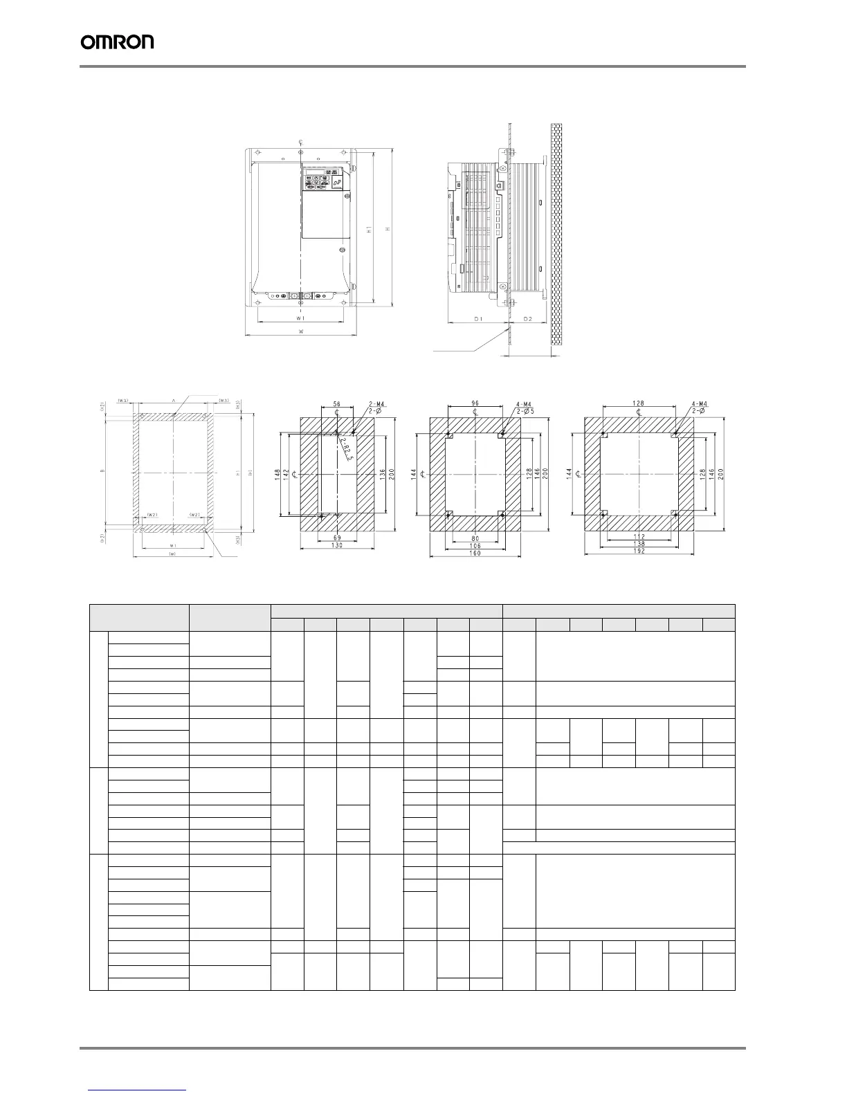
Heatsink attachment and Panel cut dimensions
VZA@ Reference
Frame
Panel Cutting
W
H W1 H1 D1 D2 D3 Fig (W2) (W3) (H2) (H3) A B
3x200v
20P1
100-034-075
68
128
56
118
69.2
12 30
2-
20P2
20P4 100-034-076 42 50
20P7 100-034-077 62 70
21P5
100-034-079
108 96
71
58 70 3 -
22P2 79.5
24P0 100-034-080
140 128 86.5 53.5 60 4 -
25P5
100-036-300
158 286 122 272 86.6 53.4 60
1
9
9
8.5
7
140 255
27P5
2011 100-036-301
198 322 160 308 89.6 73.4 80 10 10.5 180 287
2015 100-036-302
241 380 192 362 110.6 76.4 85 14 10.5 10.5 9 220 341
1X200v
B0P1
100-034-075
68
128
56
118
69.2 12 30
2-B0P2
B0P4 100-034-076 79.2 42 50
B0P7 100-035-418
108 96
79.5
58
70
3-
B1P5 100-034-079 96
B2P2 100-034-080
140 128 98
65
4-
B4P0 100-036-357
170 158 115 Under development
3X400v
40P2 100-034-078
108
128
96
118
71 13.2 30
3-
40P4
100-036-418
28 40
40P7 79.5
58
70
41P5
100-034-079 9642P2
43P0
44P0 100-034-080
140 128 78 65 4 -
45P5
100-036-300
158 286 122 272
86.6
53.4 60
1
9
9
8.5
7
140 255
47P5
198 322 160 308 10 10.5 180 2874011
100-036-301
4015 73.4 80
Heatsink External Mounting Attachment
Mounting Panel
D3 for more
Fig 3

 Loading...


