On Call Plus
®
Blood Glucose MeterOn Call Plus
®
Blood Glucose Meter Meter DisplayMeter Display
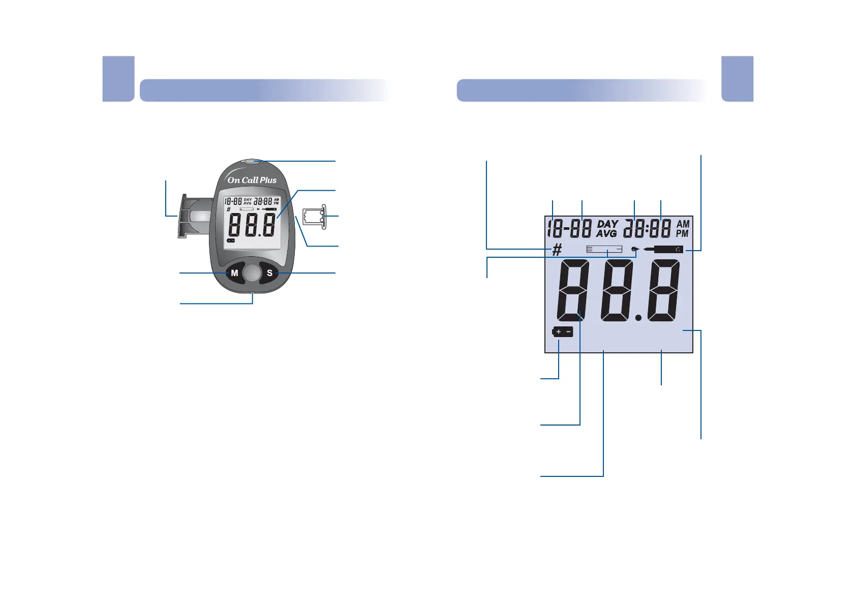
The meter reads the test strips and displays the blood glucose
concentration. Use this diagram to become familiar with all the parts of
your meter.
Liquid Crystal Display (LCD):
M Button:
S Button:
Strip Port:
Battery Carrier:
Code Chip Slot:
Code Chip:
Data Port:
Shows your test results, and helps you
through the testing process.
Recalls previous test results from the meter memory and
performs other menu selection functions.
Selects meter settings, performs other menu selection
functions.
Test strips are inserted into this area to perform a test.
The battery carrier is located on the back of the meter.
Insert the code chip here.
For coding the meter. A new code chip comes with every
box of test strips.
Not Currently Available for Use.
m
m
o
lL
l
mg
dL
l
MEM
CODE
Pound Sign (#)
Appears with the control solution
test result or when you mark an
invalid result to prevent it from
being included in the averages.
Test Strip and Blood
Drop Symbols
These two symbols
appear at the same
time to tell you when
to apply the sample.
Battery Symbol
Warns when you
should replace the
battery.
Control Solution Symbol
Indicates a control test result. A
pound sign (#) will also be
displayed when control solution
symbol appears.
Test Result Area
Indicates code
number and test
result.
Measurement Unit
Only one unit will be
displayed on your meter and
cannot be adjusted.
CODE
Appears with the
code number of the
test strips.
Month Day Hour Minutes
MEM
Shows a test result
stored in memory.
3 4
Battery Carrier
M Button
S Button
Data Port
Strip Port
Liquid Crystal
Display (LCD)
Code Chip
Code Chip Slot
m
m
o
lL
l
mg
dL
l
MEM
CODE
En En