GEAR COVER
Gear
Cover
Removal
Procedure
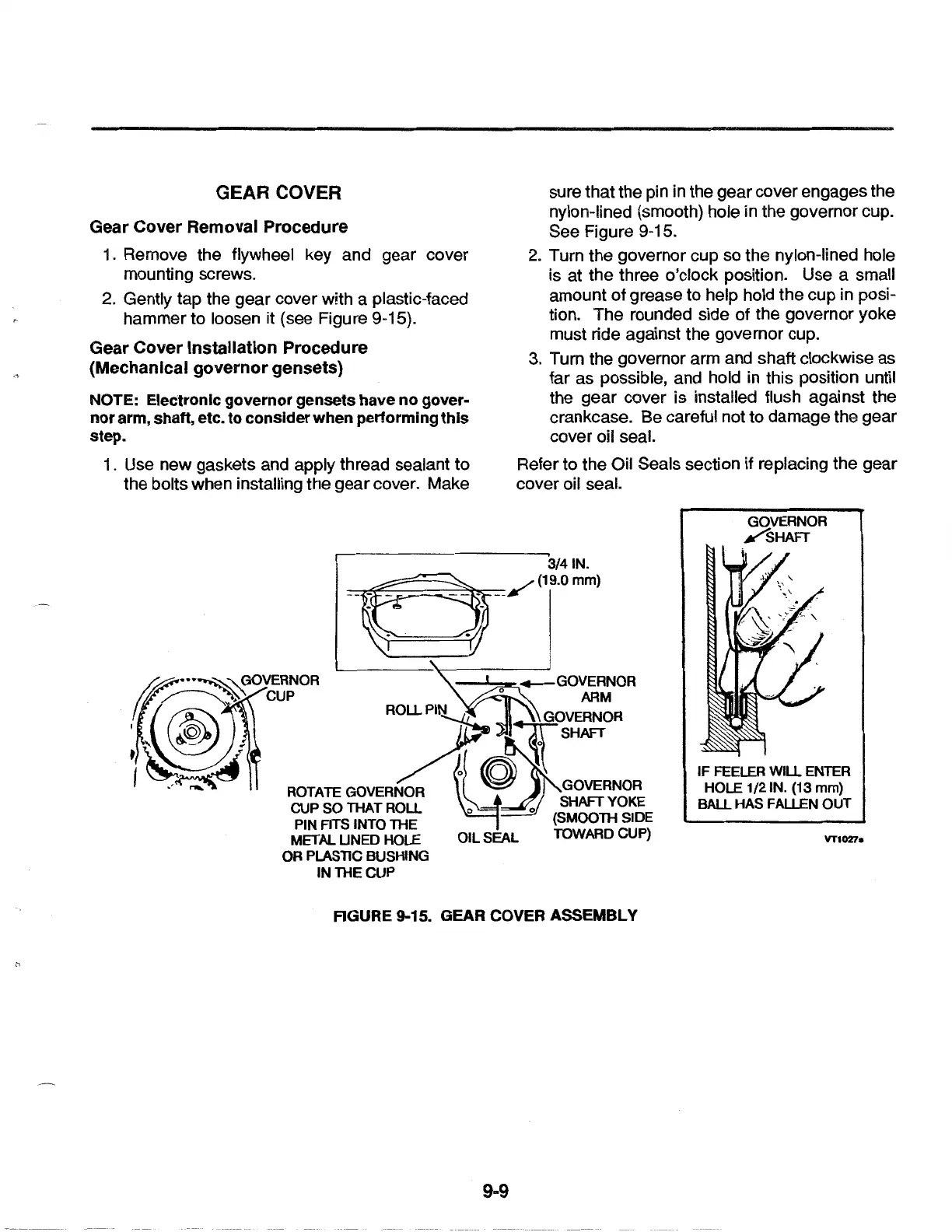
1 . Remove the flywheel key and gear cover
mounting screws.
2. Gently tap the gear cover w!th a plastic-faced
hammer to loosen it (see Figure 9-15).
Gear
Cover
Installation
Procedure
(Mechanical
governor
gensets)
NOTE: Electronic
governor
gensets have
no
gover-
nor
arm, shaft, etc.
to
consider
when performing
this
step.
1 . Use new gaskets and apply thread sealant to
the bolts when installing the
gear
cover. Make
sure that the pin in the gear cover engages the
nylon-lined (smooth) hole in the governor cup.
See Figure 9-15.
2.
Turn the governor cup so the nylon-lined hole
is at the three o'clock position. Use a small
amount of grease to help hold the cup in posi-
tion. The rounded side
of
the governor yoke
must ride against the governor cup.
3. Turn the governor arm and shaft clockwise as
far as possible, and hold in this position until
the gear cover is installed flush against the
crankcase. Be careful not to damage the gear
cover oil seal.
Refer to the Oil Seals section if replacing the gear
cover oil seal.
GOVERNOR
/sHAFT
3/41N.
=i:~:-;:;::;=:;:::~'F=--/
(19.0 mm)
RGURE 9-15. GEAR COVER ASSEMBLY
9-9
IF FEELER WILL ENTER
HOLE 1/21N. (13
mm)
BALL HAS FALLEN
OUT
VT1027a
 Loading...