VALVE SYSTEM
A properly functioning valve system is essential for
the engine to perform well. Onan gensets use an
L-head valve design,
as
shown in Figure 9-5. The
valve system may be accessed by removing the
cylinder heads and valve covers on top
of
the en-
gine.
A valve spring compressor must
be
used to
remove the va!ves (see Figure 9-6) from the cylin-
der
block. Use the procedures described below to
inspect
and service the valve system.
FIGURE 9-6.
VALVE
SPRING COMPRESSOR
Valve Inspection Procedure
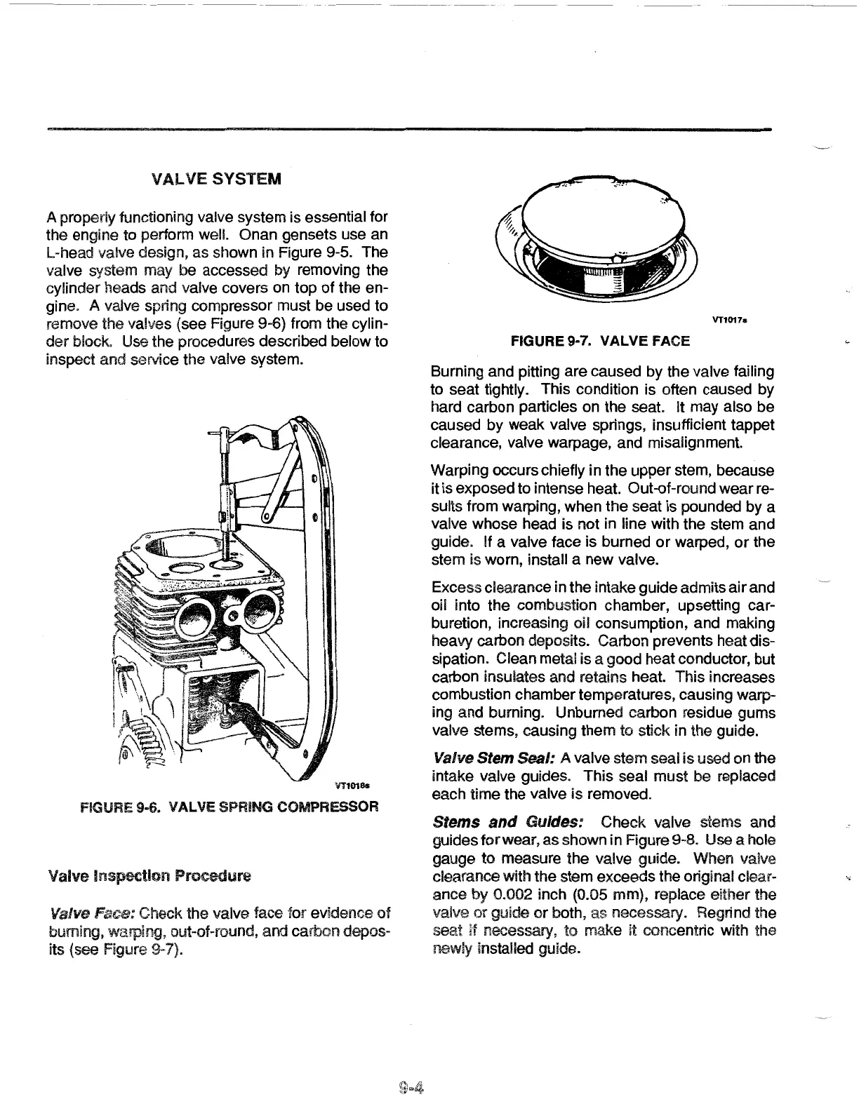
Valve Face: Check the valve face for evidence
of
burning, warping, out-of-round, and carbon depos-
its {see Figure 9-7).
VT1017s
FIGURE 9-7.
VALVE
FACE
Burning and pitting are caused by the valve failing
to seat tightly. This condition is often caused by
hard carbon particles
on
the seat. It may also
be
caused by
weak
valve springs, insufficient tappet
clearance, valve warpage,
and
misalignment.
Warping occurs chiefly
in
the
upper
stem, because
it is exposed
to
intense heat. Out-of-round
wear
re-
sults from warping,
when
the
seat is pounded by a
valve whose head is not in line with the stem and
guide. If a valve face is burned
or
warped,
or
the
stem
is worn, install a
new
valve.
Excess clearance in the intake guide admits
air
and
oil into
the
combustion chamber, upsetting car-
buretion, increasing oil consumption, and making
heavy carbon deposits. Carbon prevents heat dis-
sipation. Clean metal is
a
good
heat conductor, but
carbon insulates and retains heat. This increases
combustion chamber temperatures, causing warp-
ing
and
burning. Unburned carbon residue gums
valve stems, causing them
to stick in the guide.
Valve Stem Seal: A valve stem seal
is
used on the
intake valve guides.
This
seal
must
be replaced
each time
the
valve
is
removed.
Stems
and
Guides:
Check
valve stems and
guides
for
wear,
as
shown
in
Figure 9-8. Use a hole
gauge
to
measure
the
valve guide. When valve
clearance with
the
stem exceeds
the
original clear-
ance
by 0.002 inch (0.05 mm), replace either the
valve
or
guide
or
both,
as
necessary. Regrind the
seat
if
necessary,
to
make
it concentric with the
newly installed guide.
 Loading...