GOVERNOR CUP {MECHANICAL)
Governor
Cup
Removal
Procedure
1.
Remove the gear cover,
as
described above.
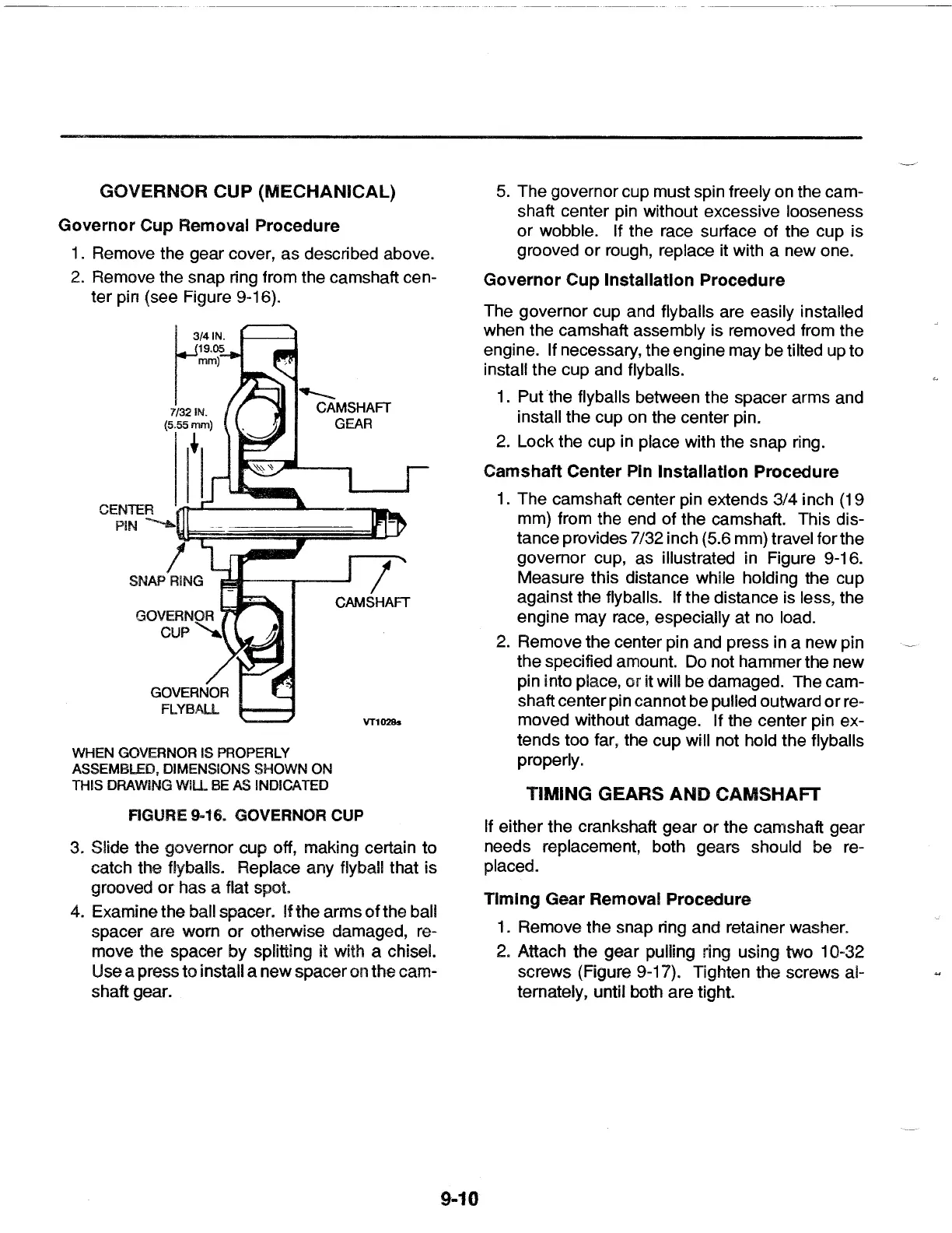
2.
Remove the snap ring from the camshaft cen-
ter pin (see Figure 9-16).
CENTER
19.05
mm)
r
l 3/41N.
7/321N.
(5.55mm)
I t
I
PIN
...._,_\{b~:§§~~~§::l..l-J
WHEN GOVERNOR IS PROPERLY
ASSEMBLED, DIMENSIONS SHOWN
ON
THIS DRAWiNG
WIU.
BE AS INDICATED
CAMSHAFT
VT1028s
FIGURE 9·16. GOVERNOR CUP
3. Slide the governor cup off, making certain to
catch the flyballs. Replace any flyball that is
grooved
or
has a flat spot.
4.
Examine the ball spacer. If the arms of the ball
spacer are worn or otherwise damaged, re-
move the spacer by splitting
it with a chisel.
Use a press to install a new spacer on the cam-
shaft gear.
9-10
5.
The governor cup must spin freely on the cam-
shaft center pin without excessive looseness
or wobble. If the race surface of the cup is
grooved
or
rough, replace it with a new one.
Governor
Cup
Installation
Procedure
The governor cup and flyballs are easily installed
when the camshaft assembly is removed from the
engine. If necessary, the engine may be tilted up to
install the cup and flyballs.
1 . Put
the
flyballs between the spacer arms and
install the cup on the center pin.
2.
Lock the cup
in
place with the snap ring.
Camshaft
Center Pin
Installation
Procedure
1.
The camshaft center pin extends 3/4 inch (19
mm) from the end of the camshaft. This dis-
tance provides 7/32 inch (5.6 mm) travel for the
governor cup, as illustrated in Figure 9-16.
Measure this distance while holding the cup
against the flyballs. If the distance is less, the
engine may race, especially at
no
load.
2.
Remove the center pin and press in a new pin
the specified amount.
Do
not hammer the new
pin into place, or
it will be damaged. The cam-
shaft center pin cannot be pulled outward
or
re-
moved without damage. If the center pin ex-
tends too far, the cup will not hold the flyballs
properly.
TIMING GEARS
AND
CAMSHAFT
If either the crankshaft gear or the camshaft gear
needs replacement, both gears should be re-
placed.
Timing
Gear Removal
Procedure
1.
Remove the snap ring and retainer washer.
2.
Attach the gear pulling ring using two 10-32
screws (Figure 9-17). Tighten the screws al-
ternately, until both are tight.
 Loading...