SPARK PLUGS
(fOP
ACCESS
TO
FRONT
AND
REAR PLU )
CARBURETOR
WITH AUTOCHOKE
(AUTOCHOKEIFUEL
PUMP RELAY K4 BEHIND
CARBURETOR)
OIL DRAIN KNOB
(3/8 INCH SQUARE DRIVE)
POSITIVE ( +)
BATTERY
CONNECTION
NEGATIVE (-)BATTERY
CABLE CONNECTION
FUEL
INLET
.25 INCH HOSE (GASOUNE)
·~~V"
.25 INCH NPTF (LPG)
AC
OUTPUT LEADS
SO
INCHES
(1.5
M)
LONG
M1801-3s
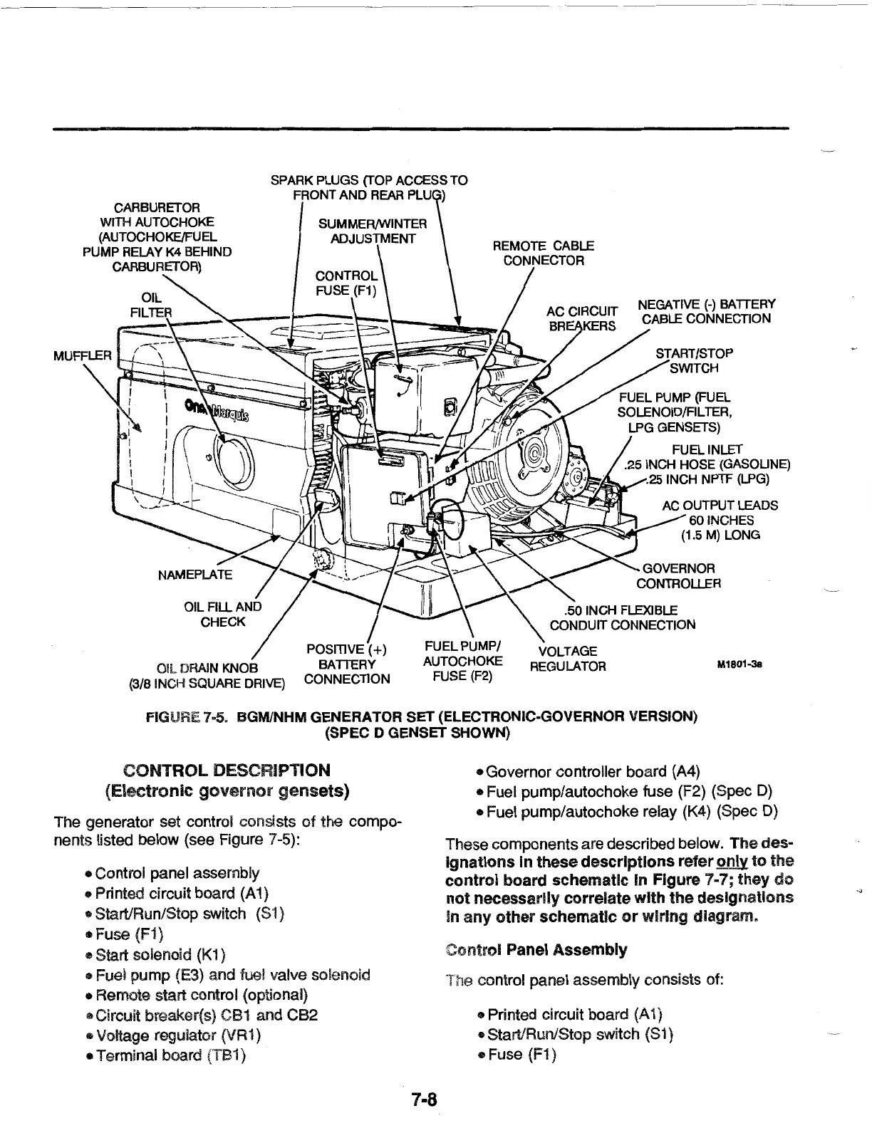
FIGURE
7D5.
BGM/NHM GENERATOR SET (ELECTRONIC-GOVERNOR VERSION)
(SPEC D GENSET SHOWN)
CONTROL DESCRIPTION
(Electronic
governor
gensets)
The generator set control consists
of
the compo-
nents listed below (see Figure 7-5):
• Control panel assembly
• Printed circuit board
(A
1)
• Start/Run/Stop switch (81)
• Fuse
(Fi)
e Start solenoid
{K1
)
• Fuel pump {E3) and fuel valve solenoid
• Remote start control (optional)
• Circuit breaker(s)
CB1
and CB2
• Voltage regulator (VR1)
• Terminal board (TB1)
1·8
• Governor controller board {A4}
• Fuel pump/autochoke fuse (F2) (Spec
D)
• Fuel pump/autochoke relay (K4) (Spec
D)
These components are described below. The des-
Ignations In these descriptions refer
only
to
the
control board schematic In Figure 7-7; they
do
not
necessarily correlate
with
the designations
In
any
other
schematic
or
wiring diagram.
Control Panel Assembly
The control panel assembly consists of:
• Printed circuit board
(A
1)
• Start/Run/Stop switch (S1)
• Fuse (F1)
 Loading...