LEFT* RIGHT*
C1002s
*
AS
VIEWED
FROM
FRONT OF ENGINE
FIGURE
9~2.
BGM CYLINDER HEAD
TIGHTENING SEQUENCE
Assembly
Procedure (NHM)
1 . Use new head gaskets, and clean both the
heads and the cylinder block thoroughly where
the gaskets rest.
2.
Place a head gasket on the cylinder head and
align the stud holes in the gasket with the stud
holes in the cylinder head. While holding the
gasket against the cylinder head, carefully in-
stall the cylinder head on the engine. Do not
attempt
to
slide the gasket over the studs with-
out the cylinder head behind
it or the gasket
may tear.
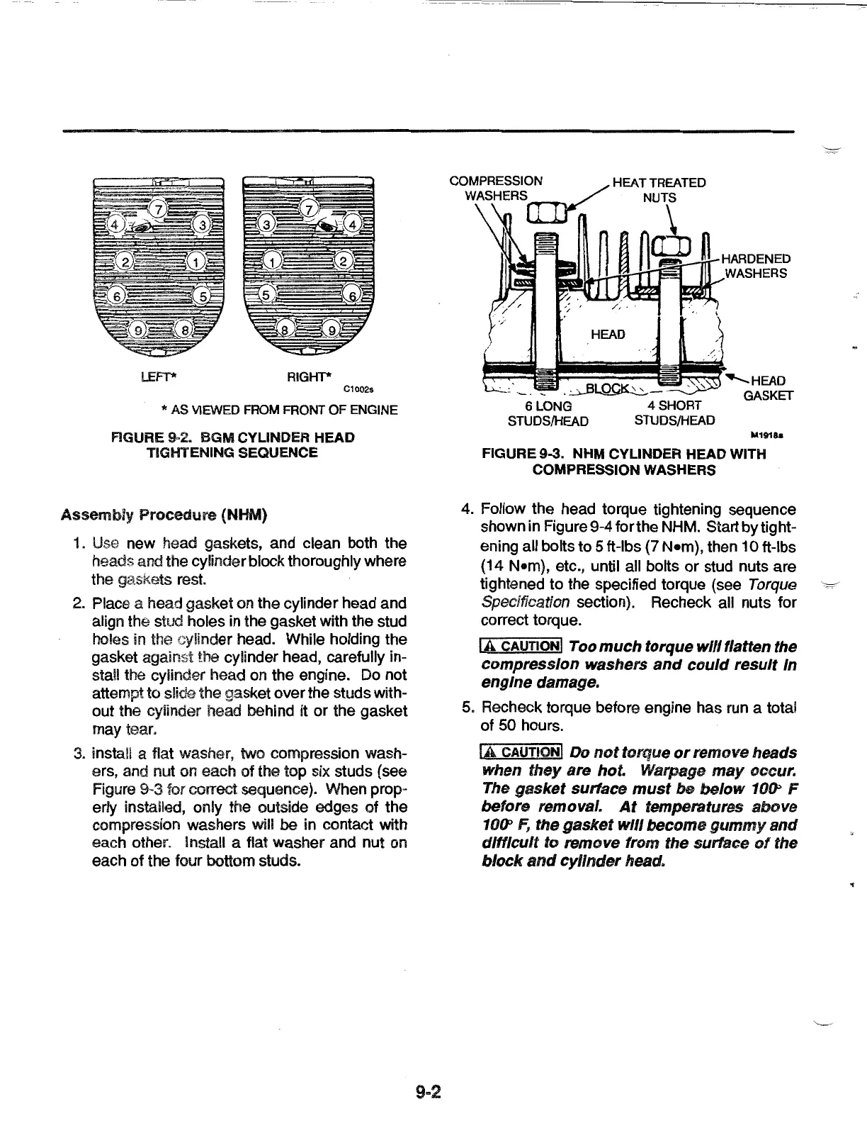
3. install a flat washer, two compression wash-
ers, and nut on each
of
the top six studs (see
Figure 9-3 for correct sequence). When prop-
erly installed, only the outside edges
of
the
compression washers will
be
in contact with
each other. Install a flat washer and nut on
each
of
the four bottom studs.
9-2
COMPRESS!~./
HEAT
TREATED
WASHERS
(llj
II NUTS
HEAD
-~~-
6 LONG 4 SHORT
STUDS/HEAD STUDS/HEAD
........._HEAD
GASKET
M191h
FIGURE 9-3. NHM CYLINDER HEAD WITH
COMPRESSION WASHERS
4. Follow the head torque tightening sequence
shown in Figure 9-4 for the NHM. Start
by
tight-
ening all bolts to
5 ft-lbs (7 N•m), then 10 ft-lbs
(14 N•m), etc., until all bolts
or
stud nuts are
tightened to the specified torque (see
Torque
·~
Specification section). Recheck all nuts for
correct torque.
lA CAUTION I
Too
much torque
will
flatten the
compression washers
and
could
result In
engine damage.
5. Recheck torque before engine has run a total
of
50 hours.
lA CAUTION! Do
not
torque
or
remove heads
when they are hot. Warpage
may
occur.
The gasket surface
must
be
below
10~
F
before removal.
At
temperatures above
10~
F,
the gasket
will
become
gummy
and
difficult
to remove from the surface
of
the
block
and
cylinder
head.
..
 Loading...