DECREASE SPEED
INCREASE SPEED
.
GOVERNO~
ARM
//
EXTENSION
t
MAXIMUM
DEGREASE
SPEED
SPEED STOP
$1
&GOVERNOR
L
MINIMUM SPEED
STOP
-
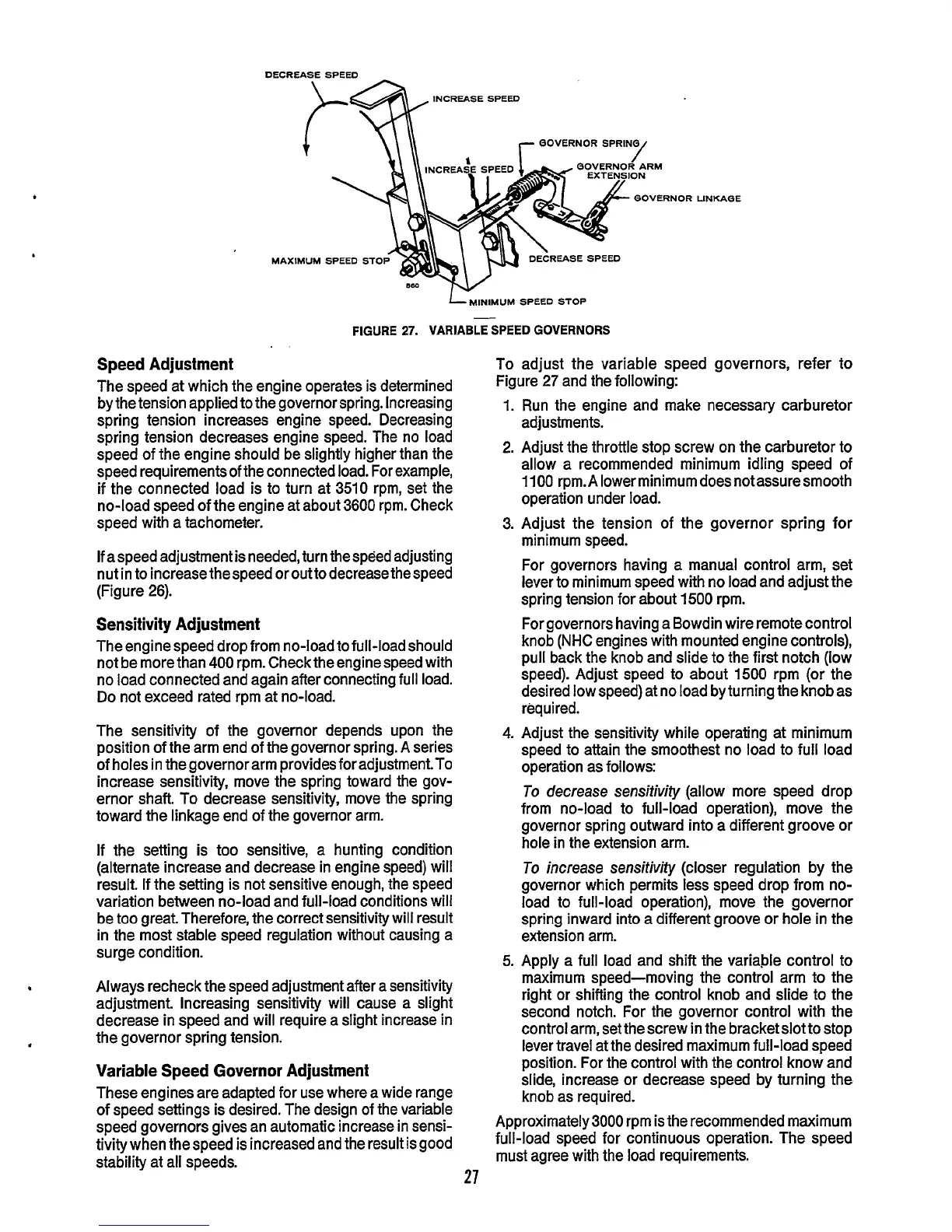
FIGURE
27.
VARIABLE
SPEED
GOVERNORS
Speed Adjustment
The speed at which the engine operates is determined
by the tension applied
to
the governor spring. Increasing
spring tension increases engine speed. Decreasing
spring tension decreases engine speed. The no load
speed of the engine should be slightly higher than the
speed requirements of the connected load. For example,
if the connected load is to turn at 3510 rpm, set the
no-load speed of the engine at about 3600 rpm. Check
speed with a tachometer.
If aspeed adjustment is needed, turn the speed adjusting
nut in to increasethespeed orouttodecreasethespeed
(Figure
26).
Sensitivity Adjustment
The engine speed drop from no-load
to full-load
should
not be more than
400
rpm. Check the engine speed with
no load connected and again after connecting full load.
Do not exceed rated rpm at no-load.
The sensitivity of the governor depends upon the
position of the arm end of the governor spring.
A
series
of holes in the governor arm provides foradjustment.To
increase sensitivity, move the spring toward the gov-
ernor shaft. To decrease sensitivity, move the spring
toward the linkage end of the governor arm.
If
the setting
is
too sensitive, a hunting condition
(alternate increase and decrease in engine speed) will
result. If the setting is not sensitive enough, the speed
variation between no-load and full-load conditions will
be too great Therefore, the correct sensitivity will result
in the most stable speed regulation without causing a
surge condition.
Always recheck the speed adjustment after a sensitivity
adjustment. Increasing sensitivity
will
cause a slight
decrease in speed and will require a slight increase in
the governor spring tension.
Variable Speed Governor Adjustment
These engines are adapted for use where a wide range
of speed settings is desired. The design of the variable
speed governors gives an automatic increase in sensi-
tivity when the speed is increased and the result is good
stability at all speeds.
27
I
JNKABE
To adjust the variable speed governors, refer to
Figure
27
and the following:
1.
2.
3.
4.
5.
Run the engine and make necessary carburetor
adjustments.
Adjust the throttle stop screw on the carburetor to
allow a recommended minimum idling speed of
1100 rpm.
A
lower minimum does not assure smooth
operation under load.
Adjust the tension of the governor spring for
minimum speed.
For governors having a manual control arm, set
lever to minimum speed with no load and adjust the
spring tension for about 1500 rpm.
For governors having a Bowdin wire remote control
knob
(NHC
engines with mounted engine controls),
pull back the knob and slide to the first notch (low
speed). Adjust speed to about
1500
rpm (or the
desired low speed) at no load by turning the knob as
required.
Adjust the sensitivity while operating at minimum
speed to attain the smoothest no load to full load
operation as follows:
To
decrease sensifivity (allow more speed drop
from no-load to full-load operation), move the
governor spring outward into a different groove or
hole in the extension arm.
To
increase sensitivity (closer regulation by the
governor which permits less speed drop from no-
load to full-load operation), move the governor
spring inward into a different groove or hole in the
extension arm.
Apply a full load and shift the variable control to
maximum speed-moving the control arm to the
right or shifting the control knob and slide to the
second notch. For the governor control with the
control arm, set the screw
in
the bracket slot to stop
lever travel at the desired maximum full-load speed
position. For the control with the control know and
slide, increase or decrease speed by turning the
knob as required.
Approximately3000 rpm is the recommended maximum
full-load speed for continuous operation. The speed
must agree with the load requirements.
 Loading...

