Circumferential grooves in the main bearings supply
oil to connecting rod bearings through drilled pas-
sages from each main journal.
A
drilled passage
connects the front main bearing oil supply to the front
camshaft bearing; rear cam bearing is splash lubrica-
ted. Oil overflow from the bypass valve provides
lubrication to the camshaft drive gears.
Normal oil pressure should be
30
psi
(207
kPa) or
higher when the engine is at normal operating temper-
ature. If pressure drops below this value at governed
speed, inspect oil system for faulty components.
Check oil pump thoroughly for worn parts. Prime the oil
pump with lubeoil before reinstalling. Except for gaskets
and pick-up cup, component parts
of
the pump are not
available individually. Install a new pump assembly
if
any parts are worn.
.
Oil
By-Pass
Valve
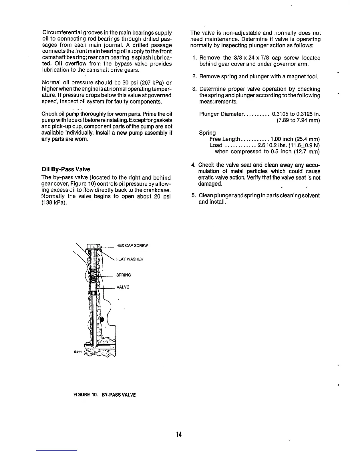
The by-pass valve (located to the right and behind
gearcover, Figure
10)
controls oil pressure byallow-
ing excess oil to flow directly back to the crankcase.
Normally the valve begins to open about
20
psi
(1
38 kPa).
HEX
CAP
SCREW
FLAT
WASHER
SPRING
VALVE
The valve is non-adjustable and normally does not
need maintenance. Determine if valve is operating
normally by inspecting plunger action as follows:
1.
Remove the 3/8
x
24
x
7/8
cap screw located
behind gear cover and under governor arm.
2.
Remove spring and plunger with a magnet tool.
.
3. Determine proper valve operation by checking
thespring and plunger according to the following
measurements.
.
Plunger Diameter..
. . .
.
. . . .
0.3105 to 0.3125 in.
(7.89
to
7.94
mm)
Spring
Free Length..
.
. .
. . .
.
.
.
1.00
inch
(25.4
mm)
Load
.
..
.
.
..
.
.
. . .
2.620.2
Ibs.
(11.6kO.9
N)
when compressed to
0.5
inch
(12.7
mm)
4.
Check the valve seat and clean away any accu-
mulation of metal particles which could cause
erratic valve action. Verify that the valve seat is not
damaged.
5.
Clean plungerand spring in partscleaning solvent
and install.
FIGURE
10.
BY-PASS VALVE
14