92
GB
8 Dismantling / Mounting in Case of Service
1505093, Edition 2012-05, Version 5
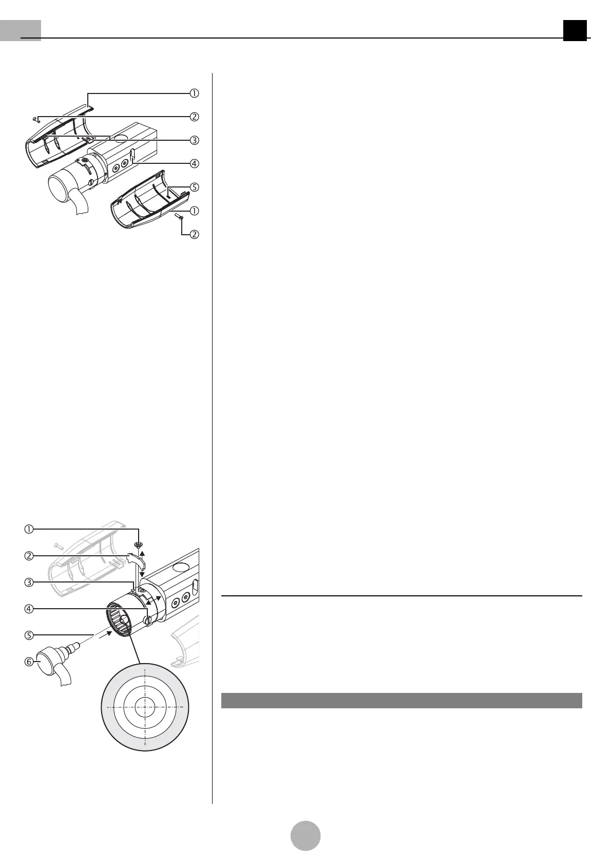
Figure 17: Mounting the cover panels Mounting the cover panels
(See "Figure 17")
9. Position the cover panel 1 with the internal guide 5 in such a way that the guide 5
protrudes into the adjustment hole 4.
10. Gently push the cover panel 1 and fasten it to the spring arm using the countersunk
Phillips screw M3 x 6 mm 2.
11. Gently push the second cover panel 1 so that the 4 straps 3 snap into each other.
12. Screw the cover panel 1 to the spring arm using the countersunk Phillips screw
M3 x 6 mm 2.
13. Check that the cover panels 1 are securely in place.
•The cover panels 1 must sit tightly on the spring arm without any gaps.
Marking
If you do not mount another end device (e.g. OR lamp) directly after dismantling, the plug
coupling in the LCH spring arm 6 is energised whilst the mains supply is switched on.
1. Mark the mains supply in the room with a warning sign:
ELECTRIC SHOCK HAZARD – DO NOT SWITCH ON THE POWER SUPPLY!
2. Mount the end device (e.g. OR lamp) later as described in
“Chapter 8.8” on page 92
.
8.8 Mounting the end device to the LCH spring arm
Follow the safety instructions
Follow the general safety instructions prescribed in
“Chapter 8.1” on page 80
.
Maximum loading capacity
Calculate the maximum loading capacity as described in
“Chapter 8.2” on page 81
.
Dismantling the cover panels
1. Dismantle the cover panels as described in
“Chapter 8.7” on page 91
.
Preparing the installation
Figure 18: Version with 3-pole plug cou-
pling
(See "Figure 18")
2. Unscrew the Allen countersunk screw M4 x 4 mm 1 and push the securing ring for
the securing segment 3 backwards.
3. Remove the securing segment 2 using a suitable slotted screwdriver.
4. Slightly unscrew the 2 brake screws 4 so that they no longer protrude into the fitting
aperture of the spring arm.
NOTE – Different plug couplings
Depending on the version of the end device (e.g. flat screen, OR lamp, etc.), the LCH
spring arm 6 is equipped with a 3-, 5- or 7/9-pole plug coupling.
Only for version with 3-pole plug coupling
(See "Figure 18")
Damage to the adaptation / end device
Grease the pivot and the pivot groove before mounting the end device.
1. Grease the pivot groove and the pivot 6 using a suitable anti-friction bearing grease
(e.g. Optimol).
NOTICE