Owner’s Manual for ONICON Insertion Turbine Flow Meters • September 27, 2001
5
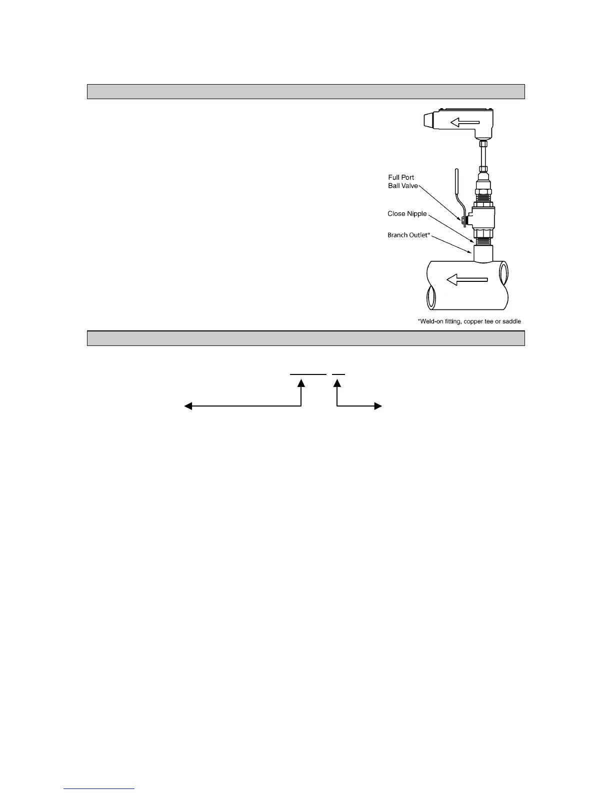
1.4 INSTALLATION HARDWARE
All ONICON insertion type meters can be installed and
removed via a 1” or larger full port ball valve without system
shutdown. The terms “Standard” and “Hot Tap” refer to the
installation method of the isolation valve kit only.
Standard Installation Hardware: For new construction or
scheduled shutdown. Once kit is installed, the flow meter can
be installed or removed without system shutdown.
Hot Tap Installation Hardware: For applications which
require the access hole in the pipe to be drilled through the
valve using a wet tap drilling machine, while the hydronic
system is pressurized and operating.
1.5 MODEL NUMBERING SYSTEM
F(B)-XX
YY
SERIES OUTPUT SIGNAL
F-11 Single Turbine, Insertion Type
F-12 Dual Turbine, Insertion Type
FB-12 Bi-Directional, Insertion Type
F-13 Inline Turbine Meter
Example: “F-1210” = Dual turbine, analog output
00 Frequency Output (15 V pulse)
For connection to Onicon display or BTU
meter only. Signal is too fast for most
building control systems (0-300 hz).
10 Analog Output (non-isolated)
Provides both 4-20 mA and 0-10 V
outputs. Most commonly used output
type. (3-wire connection)
11 Isolated Analog Output
Provides both 4-20 mA and 0-10 V
outputs. Signal ground is isolated from
power supply and pipe ground. (4-wire
connection)
20 Divided Output
(Solid state dry contact)
Provides an isolated binary/digital output.
Signal is divided to limit the maximum
frequency. For rate/totalization.
30 Scaled Output
(Solid state dry contact)
Provides an isolated binary/digital output
scaled to provide one pulse per desired
unit volume (i.e.: 1 pulse = 10 gal.).
Ideal for totalization applications.
 Loading...


