A d j u s t m e n t M a n u a l I
2
C
Item VCO Adjustment Adj.Process 2AL
3G(UE-DLX)
M o d e l ALL
Measuring
Equipment
* SG (Signal Generator)
* Digital multimeter
* CRO
Preparation
before Adj.
Adjustment
Procedure 1) Switch ON the TV Set.
2) Select colour bar pattern {carrier frequency
of 38.9MHz} from pattern generator.
3) Connect this signal to the input of Saw
Filter(after disconnecting IF output of
Tuner)
4) Connect Digital Multimeter to AFC
out(pin no. 2 of VCD IC52771, IC201)
5) Adjust VCO coil in such a way that
Digital Multimeter shows 4V(sudden
change in voltage reading from 8V)
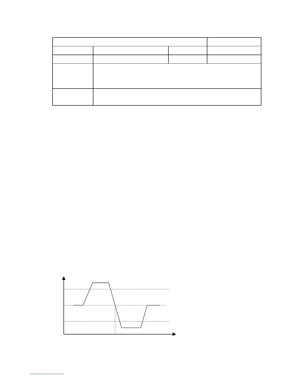
This voltage should be adjusted whenever
there is sudden fall from 8V to 1V as
shown
NOTE
* use non-metallic adjustment tool (eg~ceramic) for adjustment.
* Correct AFT voltage alignment can be confirmed by monitoring
proper waveform at pin no. 38 of VCDIC 52771 IC no. 201./CRO
can be also connected to Video OUT terminal.
8V
10