28
Connection for multiple-room remote control
Do not plug in the power cord until all connections have been made.
Make connections as shown in the Connection Diagram below. Make sure all components are correctly connected.
■
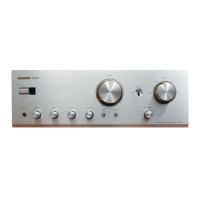
Connecting components equipped with Onkyo connectors
■
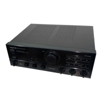
Connecting components not equipped with Onkyo connectors
MAIN ROOM SUB ROOM
Remote
controller
A-DS650
Speaker
(Main room)
Speaker
(Main room)
3. Remote Sensor
HR-10
2. Speaker
(Sub-room)
2. Speaker
(Sub-room)
1. Onkyo Components
1. Set up the Onkyo components.
2. Connect the sub-room speaker cables
to the FRONT REMOTE SPEAKERS
terminals on the A-DS650.
3. Install Remote Sensor HR-10 in the
sub-room, then connect it to the A-
DS650.
MAIN ROOM SUB ROOM
Power
supply
Remote
controller
A-DS650
3. Remote Sensor
HR-10
6. Remote Emitter
Head HE-10
Speaker
(Main room)
1. Components
4. Remote Emitter
HE-50 (AC)
Speaker
(Main room)
5. Components
2. Speaker
(Sub-room)
2. Speaker
(Sub-
room)
1. Connect the components to the A-
DS650.
Make the connections described above
in steps 2 through 3.
4. Install the Remote Emitter HE-50
(AC) so that its sensor is directed
toward these components, then con-
nect it to the A-DS650.
(Connect the AC adapter to the
Remote Emitter.)
To operate components positioned out of
range of the emitter:
5. Connect these components to the A-
DS650.
6. Install Remote Emitter Head HE-10 so
that its sensor is directed toward these
components, then connect it to the
HE-50 (AC).
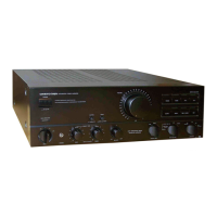
A-DS650
2
Remote Emitter
HE-50(AC)
Remote Emitter
Head HE-10
AC adapter
SUB ROOM
Speaker Remote (Sub Room)
3
6
4
Remote sensor
HR-10
Green Terminal
OUT
IN
REMOTE CONTROL
R
L
FRONT
SPEAKERS
MAIN
CENTER
SPEAKER
IN
X
OUT
FRONT
SPEAKERS
MAIN
FRONT
REMOTE
SPEAKERS
Speaker Main
(Main Room)
R
L
FRONT REMOTE SPEAKERS
Connecting diagram
 Loading...